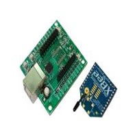
XBee USB adapter(CP) + XBee module
Description: This is a simple to use, USB to serial base unit for the XBee line. This unit works with all XBee modules including the Series 1 and Series 2.5, standard and Pro version. Plug the unit into the XBee Explorer, attach USB cable, and you will have direct access to the serial and programming pins on the XBee unit.The board also has an CP USB to Serial chip on it, meaning you can connect it to your computer via USB.The CP is connected such that you are able to reprogram the XBee modules to change the firmware. The board is powered by the USB cable.This board come up with the XBee XB24-Z7WIT-004 module from Digi. The new Series 2B improves upon the power output and data protocol of the Series2. Series 2B modules allow you to create complex mesh networks based on the XBee ZB ZigBee mesh firmware. These modules allow a very reliable and simple communication between microcontrollers, computers, systems, really anything with a serial port! Point to point and multi-point networks are supported. Features: � USB Connectivity. � USB Powered. � Small footprint. � All XBee pins broken out. � Reset button. � Onboard 3.3V regulated supply. � Small footprint. Specifications for XBee module: � 3.3V @ 295mA � 250kbps Max data rate. � 63mW output ( 17dBm). � 1 mile (1600m) range. � Built-in antenna. � Fully FCC certified. � 6 10-bit ADC input pins. � 8 digital IO pins . � 128-bit encryption. � Local or over-air configuration. � AT or API command set. Package Content: � XBee USB adapter board. � XBee module.(Series 2).
...more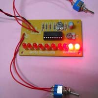
Electronic Float
We are a trustworthy Manufacturer and Supplier of Electronic Float, based in India. Electronic Float can be used with many mechanical floats. The electronic shaft connected to the mechanical float rotates as the float rotates. The rotation of the shaft makes the circuit to switch on ten LEDs connected to the ten outputs of linear voltage display IC1, which indicates the position of rotation of the shaft. The lowest LED D10 lights when rotation is at minimum level. As the rotation increases other LEDs glows one by one. When the rotation reaches 90o, the uppermost LED D1 illuminates. Thus by varying this electronic shaft from 0 to 90o, we can have ten indications for span of each 10o.About the Circuit : The operation of the circuit is based on linear voltage display IC1, which consists of 11 op-amps as comparators connected internally. The input of IC1 is directly derived from the battery voltage via potential divider R4-R5-P1-P2. This variable input is about 3V for battery potential of 12V. The display range depends on the internal voltage reference and resistors R1-R3. When pot P1 is at minimum position, the first op-amp of IC1 gets triggered and LED D10 glows. As the P1 varies from 0 to 90o, op-amp gets triggered sequentially and LEDs D10 to D1 glows one by one or in dot mode. You can see the display in bar mode also through toggle switch S2. When S2 is ON all ten LEDs glows and turns off one by one as P1 varies. The circuit requires a DC power supply of 12V and the current consumption is about 30mA.
...more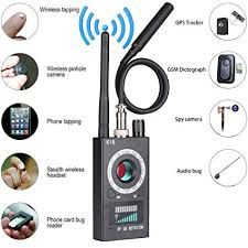
Wireless Listening Bug
Wireless Listening Bug is used to listen to the voices of people sitting in the nearby room on fm radio. The circuit can detect both incoming and outgoing calls, SMS and video transmission even if the mobile phone is kept in the silent mode. The moment the bug detects RF transmission signal from an activated mobile phone, it starts sounding a beep alarm and the LED blinks. The alarm continues until the signal transmission ceases. An ordinary RF detector using tuned LC circuits is not suitable for detecting signals in the GHz frequency band used in mobile phones. The transmission frequency of mobile phones ranges from 0.9 to 3 GHz with a wavelength of 3.3 to 10 cm. This handy, pocket-size mobile transmission detector can sense the presence of an activated mobile phone from a distance of one and-a-half meters. So it can be used to prevent use of mobile phones in examination halls, confidential rooms, etc. It is also useful for detecting the use of mobile phone for spying and unauthorized video transmission. So a circuit detecting gigahertz signals is required for a mobile bug. Here the circuit uses a 0.22µF disk capacitor (C3) to capture the RF signals from the mobile phone. The lead length of the capacitor is fixed as 18 mm with a spacing of 8 mm between the leads to get the desired The disk capacitor along with the leads acts as a small gigahertz loop antenna to collect the RF signals from the mobile phone Op-amp IC CA3130 (IC1) is used in the circuit as a current-to-voltage converter with capacitor C3 connected between its inverting and non-inverting inputs. It is a CMOS version using gate-protected p-channel MOSFET transistors in the input to provide very high input impedance, very low input current and very high speed of performance. The output CMOS transistor is capable of swinging the output voltage to within 10 mV of either supply voltage terminal. This will upset the balanced input of IC1 and convert the current into thecorresponding output voltage. Capacitor C4 along with high-value resistor R1 keeps the non-inverting input stable for easy swing of the output to high state. Resistor R2 provides the discharge path for capacitor C4. Feedback resistor R3 makes the inverting input high when the output becomes high. Capacitor C5 (47pF) is connected across ‘strobe’ (pin 8) and ‘null’ inputs (pin 1) of IC1 for phase compensation and gain control to optimize the frequency response. When the mobile phone signal is detected by C3, the output of IC1 becomes high and low alternately according to the frequency of the signal as indicated by LED1. This triggers monostable timer IC2 through capacitor C7. Capacitor C6 maintains the base bias of transistor T1 for fast switching action. The low-value timing components R6 and C9 produce very short time delay to avoid audio nuisance. Assemble the circuit on a general purpose PCB as compact as possible and enclose in a small box like junk mobile case. As mentioned earlier, capacitor C3 should have a lead length of 18 mm with lead spacing of 8 mm. Carefully solder the capacitor in standing position with equal spacing of the leads. The response can be optimized by trimming the lead length of C3 for the desired frequency. You may use a short telescopic type antenna. Use the miniature 12V battery of a remote control and a small buzzer to make the gadget pocket-size. The unit will give the warning indication if someone uses mobile phone within a radius of 1.5 meters.
Type : Listening Bug
Finishing : Polished
Color : Available in Many Colors
Warranty : 6 Months
Material : Metal
Packaging Type : Packed in Boxes
...more
Whistle Responder
The Whistle Responder beeps when it hears your whistle and this amazing invention is priced at a meager Rs 350/-. Some 20 years ago it was common to see small key-holders emitting an intermittent beep for a couple of seconds after its owner whistled. These devices contained a special purpose IC and therefore were not suited to home construction. The present circuit is designed around a general purpose hex-inverter CMos IC and, using miniature components and 9V batteries can be enclosed in a box. It is primarily a gadget, but everyone will be able to find suitable applications.About the circuit :This device beeps intermittently for about two seconds when a person in a range of around 5 meters emits a whistle. The first two inverters contained in IC1 are used as audio amplifiers.IC1'A' amplifies consistently the signal picked-up by the small electret-microphone and IC1'B' acts as a band-pass filter, its frequency being centered at about 1.8KHz. The filter is required in order to select a specific frequency, the whistle's one, stopping other frequencies that would cause undesired beeper operation. IC1'C' is wired as a Schmitt trigger, squaring the incoming audio signal. IC1'D' is a 2 second-delay monostable driving the astable formed by IC1'E' & IC1'F'. This oscillator generates a 3 to 5Hz square wave feeding Q1 and Buzzer (BZ), thus providing intermittent beeper operation.
Type : Digital
Material : Plastic
Shape : Rectangular
Feature : Eco Friendly
Color : Available in Many Colors
Warranty : 6 Months
...more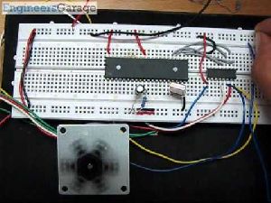
Washing Machine Timer Circuit
The washing machine having no automatic controls can be atomized to some extent by the circuit below. This is helpful in saving power and improving washing quality. In addition, it makes the homemaker free to do other chores while washing machine is doing its job. The timer gives audible warning continuously when the time is over.About the circuit :Washing Machine Timer is built around IC 4060 and inverting buffer 4049 both CMOS. Washing Machine Timer has on chip oscillator circuit, which can be finished by using external R, C components. C1, Rx*, R7 and VR1 forms the oscillator’s RC components which decides frequency and hence timing. C2, R11 provides power ON reset. Lower the frequency, higher the pulse timing. The oscillator frequency is divided by chain of 14 binary counters, which at the end of 14th stage, gives large pulse period at pin 3. Initially this output would be LO.Once the circuit power is switched ON through S1, IC-1 gets reset and starts with all counter outputs reset to LO state. Counter outputs go Hi as counting progresses.As the oscillator, frequency is divided and consecutive counter output goes high, the Hi state progresses through 14 stage counter outputs. LED D1 shows the oscillating behavior by pulsating flashes. When last counter output (Q14 at Pin 3) switches Hi, transistor T1 conducts and counter input at pin 11 is pulled LO.The output pin 3(last output of counter chain) is fed to the four inverting buffers (Ic 4049) which produces LO output at corresponding four outputs. Pin 2, 4 and 10 are connected in parallel to augment the drive capacity and drives a PZT buzzer. Fourth output at pin 6 drives the Relay through transistor T2 subsequently driving the washing machine through relay contacts.Since initially 4049 output is Hi relay is energized as soon as power is applied to the circuit through S1. After the set time delay IC 4049 outputs go LO and relay is switched OFF thereby stopping the washing machine.The time delay as per requirement can be selected by selecting resistor R1 to R6 with the help of rotary switch (one pole, 7way). Seven time delays are available to choose from. The time delay ranges can be altered by changing these resistance values. Select washing time bet.2 1/2 to 30 min. & buzzer when time laps.
Type : Circuit
Voltage : 220V
Pressure : High
Material : Plastic
...more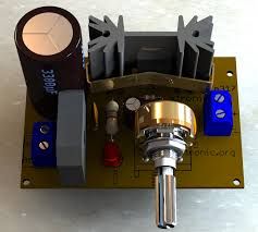
Variable Regulated Power Supply Circuit
The Variable Regulated Power Supply Circuit can provide variable output is adjustable from 1.6 volts to about 30 volts using ic LM317. This kit is based on the LM317 type integrated circuit. This is a simple, but low-ripple power supply, and an excellent project if you're starting out in electronics. It will suit your needs for most of your bench testing and prototype applications. The output is adjustable from 1.5 volts to about 30 volts. Maximum current is about 1.5 amps which is also sufficient for most of your tinkering. It is easy to build and can be pretty cheap if you have some or all the required parts.Circuit description :The 220VAC coming from the power-cord is fed to the transformer TR. The 24VAC output (approximately) from the transformer is presented to the bridge rectifier diode D1 TO D4, and here rectified from AC (Alternating Current) to DC (Direct Current). The LM317's max input voltage is 36V. so right at the maximum edge. Better to obtain a transformer with a little less voltage and be safe. A 0-18VAC transformer will still give you about 26VDC and more than anyone hobbyist ever need. The amperage of the transformer should be 1.5A or so. That way it does not get hot. The pulsating DC output from bridge is filtered via the C1 capacitor and fed to 'IN'-put of the adjustable LM317 regulator (IC1).The output of this regulator is your adjustable voltage of 1.5 to 30 volts varied via the 'Adj' pin and the 5K pot VR1. The large value of C1 makes for a good, low ripple output voltage.D5 is a general purpose 1N4001 diode, used as a feedback blocker. It steers any current that might be coming from the device under power around the regulator to prevent the regulator from being damaged. Such reverse currents (spikes) usually occur when devices are powered down. The 'ON' Led will be lit via the 1.8K (1800 ohm) resistor R1. The current through the led will be between 12 - 20mA @ 2V depending on the type and color Led you are using. You may need to modify the value of R1 depending on your type LED. C2 is a 0.1uF (100nF) decouple capacitor to filter out the transient noise which can be inducted into the supply by stray magnetic fields. Under normal conditions this capacitor is only required if the regulator is far away from the filter cap, but I added it anyway. C3 improves transient response. This means that while the regulator may perform perfectly at DC and at low frequencies, (regulating the voltage regardless of the load current), at higher frequencies it may be less effective. Adding this 1 uF capacitor should improve the response at those frequencies.Construction :First of all you should place on the board the resistors the capacitors , the diodes & make sure that the electrolytic capacitors & diodes are connected the right way round because they are polarized. Make a careful visual inspection for mistakes, shorts across adjacent tracks etc. and if everything seems to be all right. In our kit the secondary connection of the transformer are connected.If all is well, and you are finished assembling and soldering everything, check all connections. Check capacitors C1 & C3 for proper polarity (especially for C1, polarity reversal may cause explosion). Hookup a multi-meter to the power supply output jacks.Set the multi-meter for DC volts. Switch on (led will light, no smoke or sparks?) and watch the meter movement. Adjust potentiometer P1 until it reads on your multi-meter 15Volts. Adjust Pot until the panel meter (if so installed) also reads 15volts. The panel voltmeter is optional. When done, note any discrepancies between your multi-meter and the power supply meter at full scale (max output). Maybe there is none, maybe there is little, maybe there is a lot because of your choice of transformer but you will be aware of it. Just make sure your multi meter reading and panel meter read as close as possible.
Type : Home Ups, Modular UPS
Certification : ISI Certified
Application : Control Panels, Industrial Use, Power Cut Solution
Weight : 0-5Kg
Color : Metallic
Frequency : 50Hz, 60Hz
Automatic Grade : Automatic, Fully Automatic
Driven Type : Electric
Feature : Easy To Install, Electrical Porcelain
...more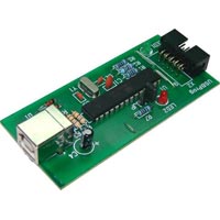
USB Programmer
We are a prominent Manufacturer and Supplier of USB Programmer. USB Programmer is configured using advanced technology, ensuring efficient performance. USB Programmer is a low cost USBASP programmer for AVR family. USB Programmer is available with us in different specifications, meeting diverse demands of the customers. USB Programmer is available at economical price.Detail : Easy to use FRC interface Works under Mac/Linux/windows platform Max 5kbps write speed
Type : Programmer
Color : Green
Feature : Eco Friendly
Finishing : Polished
Warranty : 6 Months
...more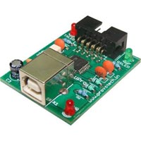
Upro ISP programmer
We are a prominent Manufacture and Supplier of Upro ISP programmer. Upro integrates advanced technology to offer reliable performance. Upro is available in different specifications, catering diverse demands of the clients. Upro is available at economical price.Detail : Onboard data transmitter/receiver indicator LEDs Compaq design Easy to use FRC interface Supports all microcontroller families Support all standard baud rates
Operating Voltage : 4.5V to 5V DC
Color : Green
Feature : Durable
Shape : Rectangular
Warranty : 6 Months
...more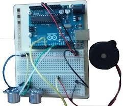
Ultrasonic Sound Burglar Alarm
Ultrasonic Sound Burglar Alarm gives alarm on interruption of Ultrasonic sound beam. The circuit arrangement for an ultrasonic burglar security system operates in accordance with the Doppler principle and comprises a transmitting transducer which is fed from an oscillator with an ac voltage and continuously transmits ultrasonic radiation during operation, a receiving transducer and a receiving circuit connected thereto and having an analysis circuit and a phase detector which continuously compares the signal received by the receiving transducer with the oscillator ac voltage to form a detection signal which is dependent upon the mutual phase angle. The detection signal is fed to the analysis circuit which responds to the ac component thereof. The circuit arrangement includes a phase-locked loop (PLL) which includes a further detector, a low-pass filter following the phase detector and an oscillator. The oscillator has its frequency controlled at a control input and may be formed as a voltage controlled oscillator (VCO). The cut-off frequency of the low-pass filter is designed to be such that only signals which can pass fundamentally without reduction are those whose frequency is lower than a critical frequency F.sub.c =c/E, where c is the speed of sound of the ultrasonic radiation in the area and E is the path of the ultrasonic radiation from the transmitting transducer to a reflective object located in the predetermined maximum range and back to the receiving transducer.Ultrasonic Sound Burglar Alarm is an ultrasonic alarm, also known as a silent alarm. This system that lets out a siren that's inaudible to the human ear. Banks typically use these types of systems. As far as home security goes, having a quick response team in place like the system's corresponding call center is an essential part of this setup. This device uses sound waves that act as motion sensors within the home. The waves are projected in beams which bounce across a room's surface areas. Passive infrared detector beams are the most commonly used, capable of detecting activity, as well as temperature changes. These beams are projected out into a room's space using a coverage lens. How this lens is configured will determine how these beams are dispersed throughout the room. As these are highly sensitive systems, proper positioning and adjustment is necessary to avoid false alarms caused by sunlight and heating systems. This unique Ultrasonic Sound Burglar Alarm makes use of the invisible, inaudible ultrasonic sound beam to detect movements. Ultrasonic transducers operate at maximum efficiency when driven at 40 kHz frequency. So an ultrasonic transmitter and receiver pair operating at 40 kHz is used to control the buzzer or the relay. The transmitter unit is built around CMOS IC CD4001 (see Fig. 1). By adjusting the 22-kilo-ohm preset (VR1), the oscillator frequency can be set to approximately 40 kHz. The ultrasonic transmitter transducer is driven by two complementary buffer stages of CD4001 and its current drain is very low. The receiver unit uses a two-stage 40 kHz preamplifier followed by switching circuit, buzzer driver, etc (see Fig. 2). Adjust VR2 in the receiver circuit till the buzzer stops sounding while the receiver senses ultrasonic sound from the transmitter. When the ultrasonic beam is interrupted by the movement of a person or any other object crossing its path, NPN transistor T4 stops conducting and transistor T5 conducts. It activates the buzzer and LED1 for three to four seconds. This duration depends on the time taken by 470µF capacitor (C9) connected at the base of transistor T5 to discharge fully through resistor R14. The burglar alarm duration can be set to a desired value with the values of C9 and R14.The alarm circuit comprising transmitter, receiver and associated circuits operates off a 9-12V regulated power supply. The receiver circuit requires regulated 12V. You can also use unregulated power supply here. Align the ultrasonic transducer such that the signal falls directly on the ultrasonic receiver. The piezobuzzer (BZ1) can be replaced with a relay to control the mains-operated alarm.
Type : Wireless Burglar Alarm
Material : Plastic
Color : Black, Blue, Grey, White
Feature : Durable
Voltage : 110V, 220V
Power Source : Electric
...more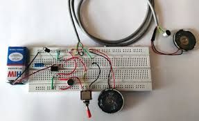
Two Way Intercom Circuit
This Two Way Intercom Circuit provides a simple way by which we can communicate in two ways i.e. send a signal as well as receive a signal. The circuit is build around timer IC555 (IC1) and low power audio amplifier IC386 (IC2). The circuit is designed in two parts. Here the circuit diagram of one part is shown in figure. The output of one unit is given to the input of other unit. The two parts are co`nnected by three way wire connection points. These points are denoted by 'S' for supply, 'O' for output and 'G' for ground.About the Circuit : When switch 'S1' is pressed, IC1 gets triggered. Hence IC1, which is connected in a stable mode, acts as a tone generator or oscillator. These oscillations generated at output pin3 are given to bypass input pin7 of IC2. The sound signals generated due to communication are received by condenser mic connected at audio input pin3 of IC2. These signals are amplified by audio amplifier IC2 and the amplified output generated at pin5 is given to Loudspeaker through coupling capacitor C1. We can mute the unit by pressing switch S2. The components mentioned in the part list are only for one side. The other side of the unit uses the same components. Hence twice the components mentioned in the part list should be used except power supply. Three Core shielded wire of about 4-10 meters can be used for connections between two units. Note on IC386 :As stated earlier, IC386 is a low power audio amplifier IC, which is very inexpensive and widely used. Some of the important features of this IC are : Minimum external parts Low distortion Wide supply voltage range Two-way communication, with self-ringing facility. Power supply :The circuit requires a regulated DC power supply of 9V. For this, the power supply design is shown in figure. The assembled module of power supply is to be kept inside one intercom hand set.
Color : Available In Many Colors
Warranty : 6 Months
Type : Circuit
Feature : Durable
Finishing : Polished
...more
Two Way Communication Security System For Household
Every person wants security from an unknown person in the absence specially when children are at home. Two Way Communication Security System For Household is the specially designed circuit for such type of security. The circuit is built around infrared transmitter and receiver and intercom circuit. When any object interrupts, the infrared signal transmitted by infrared transmitter the infrared sensor in receiver circuit detects this and energizes the relay connected at the output section of the infrared receiver. As relay is, energized melody generator circuit starts generating the melody sound. Thus people inside the house gets alert that someone is at your gate. Now for your security you can start communication with that unknown person. The arrangement of speaker and microphone are such that you can easily communicate with the person outside your house. Thus you are secured from an unknown person. About the Circuit : The circuit is built around infrared transmitter and receiver, melody generator circuit and two way communication circuit as shown in the circuit diagram. Transmitter circuit : Two Way Communication Security System For Household consists of a timer IC as IC1 connected as an astable multi vibrator, driving an output transistor, which switches the IR LED D1, ON, & OFF. The duration of the transmitted light pulses is about 10ms and the repetition rate is just less than 1 KHz. The sensitivity is adjusted by adjusting preset P1.The power supply for the transmitter is not critical provided the output voltage is not greater than 9V as this could result in the maximum current rating of D1.Receiver Circuit : Receiver section comprises power supply an infrared detector module, time delay circuit with noise filter, bistable flip-flop and an output section. The infrared sensor is used for sensing the IR signal from the transmitter section. In normal operation i.e. without any interruption output at pin2 of IR sensor are high, T2 remains OFF. IC4 is not triggered. When any object interrupts the IR beam falling on sensor, pin2 goes low. Transistor T2 turns ON. Consequently, capacitor C5 starts charging through resistor R9. When voltage across capacitor C5 reaches about 3.5V, pin2 of IC4 receives a high pulse. As IC4 is two input EX-OR Gate, output at pin 3 goes high. Transistor T3 conducts and low pulse is applied to trigger pin2 of IC5. IC5 being operated in monostable mode gets triggered. Output at pin3 of IC5 goes high and relay is energized. LED D2 glows which gives visual indication. Pin 3 remains high for a time set by R12/P2/C9. This time delay is set by preset P2. The NO (Normally Open) output of relay is given to melody generator circuit, which receives supply through relay. The melody sound is heard till relay is ON. Thus, the unknown person is detected through melody sound. When ON signal is available output of sensor goes high and T2 is switched OFF. Now capacitor C5 starts discharging through R8 and voltage across it decreases to zero. When another signal arrives capacitor, C5 again charges through R9 and IC4 gets triggered again. IC3 is a regulator IC that provides a regulated voltage. Now the communication starts. The communication circuit is built around amplifier IC as IC6 and tone generator is designed using astable multivibrator IC7. As there is a two-way communication, two sets are designed. Sound signals generated due to communication are received by condenser MIC connected at audio input pin2 of IC6/IC8. These signals are amplified by audio amplifier and the amplified output generated at pin6 is given to transistor T5 and T6. The signal is again amplified and the final output is given to speaker. There is also a volume control that, can be set with the help of preset P3/P4. Switches S1 and S2 are used to start the communication. When S1 is, pressed IC7 gets triggered and oscillations start. These oscillations acts as tone input to IC6.
Type : Burglar Alarm Systems
Material : Plastic
Certification : CE Certified
Color : Black, Blue, Grey
Feature : Durable
Application : Home Security, Office Security
Warranty : 1Year
...more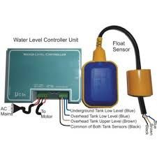
Two Tank Auto On Off Controller
Our organization has gained reputation as a Manufacturer and Supplier of Two Tank Auto On/Off Controller. Two Tank Auto On/Off Controller efficiently controls sump as well as overhead tank. Two Tank Auto On/Off Controller is specially designed for application such as hostels, apartments, hospitals, etc, where controlling the water tank is very essential. The specialty of this circuit is that it controls upper as well as lowers tanks. Motor becomes on when upper tank is empty and lower tank is at predetermined low level. In addition, it becomes off when water level in the upper tank reaches to high level or it is full. The sensors for lower and upper tank are shown in circuit diagram.About the Circuit : The circuit uses IC1, which consists of four AND gates. The Low and High sensors of upper tanks are connected to one of the inputs of two AND gates in IC1. The low- level sensor of lower tank is connected to one of the input of NAND gate in IC4 and IC3. IC2, which is wired as bistable multi vibrator gets triggered according to the logic level present at the threshold input pin6 and trigger pin2. IC3, which is a four input AND gate gets triggered when all its input are logic high which in turn drives transistor T1. In addition, there is an audible warning when lower tank is below the low level. The basic operation of the circuit is as follows : Suppose lower tank is at low level and upper tank is empty. In this case, output of IC1 at pin4 is low. As a result, IC2 is triggered and gives logic high pulse at output pin3. As all the inputs of IC3 are high, it gives output high. Transistor T1 conducts and relay becomes on. LED D2 glows, which shows that motor is on. It remains on as long as water level in upper tank reaches to High level. When upper tank reaches to High level, the output of IC1 at pin4 becomes high; IC2 gets reset and generate low pulse at pin3. As one of the input of IC3 receives logic low value, its output becomes low. T1 turns off and relay connected to the collector of T1 becomes off. In addition, LED D2 goes off and it remains off until upper tank becomes empty. Also, there is a provision for audible warning. When lower tank is below low level, the output of IC3 is low and motor is off as this water is not good for drinking. At the same time IC4 gives high output. As a result, Transistor T2 conducts and buzzer connected at the collector terminal raises alarm, which gives an indication that the lower tank is empty. Also LED D3 glows, which gives visual indication.
Type : Lighting Control System
Certification : CE Certified
Color : Available in Many Colors
Voltage : 110V
Display Type : Analogue, Digital
Frequency : 50Hz, 60Hz
Power : 1000w
Warranty : 1year
...more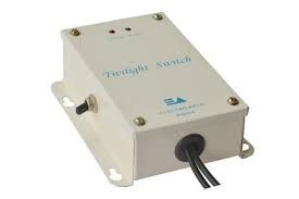
Twilight Switch
Shape : Rectangular, Square
Packaging Type : Box, Carton
Phase : Single Phase, Three Phase
...more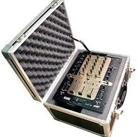
Trainer Educational Kits
We offer trainer educational kits. Our proficiency is in manufacturing and supplying of linear integrated circuits practical kits that is made in compliance with the international quality standard using the finest quality raw material and the most advanced machinery under the supervision of skilled professionals. Further, we also have a quality checking department who do specific test on various parameters in order to deliver quality assured products. Clients can avail the entire range from us at cost-effective price.
...more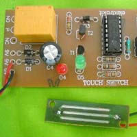
Touch Switch
Our valued clients can avail Touch Switch from us. Touch Switch makes possible to turn on/off a device by touching a metal plate successively. The circuit uses timer IC555 (IC1), which is followed by master slave JK flip- flop IC4027 (IC2). On touching the plate, IC1 gets triggered and IC2 makes output at pin1 high and low on first and second touch respectively. Accordingly relay becomes on and off successively.About the Circuit :When the metal plate is touched, IC1 performs one monostable operation. Output at pin3 of IC1 goes high. This pulse acts as a clock input at pin3 of IC2. When clock is high, master flip-flop of IC2 is enabled and data inputs (J and K inputs at pin5 and pin6 respectively) are not effective at this transition. When clock goes low, slave is enabled and data is transferred from master to slave.During the first touch, output Q at pin1 of IC2 goes high. Transistor T2 conducts and relay becomes on. Now during the second touch, output Q becomes low. Because in master slave JK flip flop output changes to the complement of last state its state at successive clock pulses. Thus T2 gets cut off and relay becomes off.The circuit also gives visual indication of touch switch using two LEDs. When Q becomes high, T1 turns ON which makes the red LED D4 turns OFF and green LED D5 glows indicates that the device is on. Similarly, when Q becomes low, T1 cuts off which makes red LED D4 to glow and green LED D5 to goes OFF. This indicates that the device becomes off.
Material : LDPE, Metal
Shape : Rectangular
Application : Touch Light
Certification : CE Certified
Color : Available in Many Colors
Surface Finishing : Coated
Feature : Easy To Fit, Electrical Porcelain
Warranty : 1 Year
...more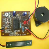
Touch Sensitive Alarm
Touch Sensitive Alarm can be used in a variety of applications. But, the most practical application is for intruder detector. The circuit uses Schmitt Trigger Inverter IC1, together with a self -oscillating piezo-electric buzzer and handful of other components. Our esteemed customers can avail Touch Sensitive Alarm at economical price.About the Circuit :IC1 consists of six inverters, out of which five are used here. One of the inverter forms an oscillator with frequency around 1MHz. The frequency is determined by R1/C2. The oscillator output is given to second inverter, which in turn is AC coupled to a full wave rectifier circuit. As long as the door handle (or a metal plate) is left untouched, the oscillator output will alternately switch the input above and below its two trigger voltages. Output will thus switch alternately low and high at clock rate to drive the rectifier circuit.When metal plate is touched, most of the signal from the oscillator will be capacitively shunted to the shield ground, which forms a pseudo earth. As a result, output of at pin6 becomes high, transistor T1 becomes on and buzzer sounds an alarm. It remains on as long as contact is made with the door handle. Also, LED D4 lights, which gives visual indication. Simple delay network consisting of P1, C1, and D3 provides minimum delay when momentary contact is made with the touch plate. The delay is varied from 2 to 20 seconds with the aid of P1.Note : External shield ground must be provided to a small aluminium foil for effective sensitivity only in case of a battery supply.
Size : 20x50inch, 22x55inch, 26x65inch
Material : Aluminium, Fiber
Shape : Rectangular
Thickness : 10-15mm, 15-20mm, 25-30mm
Color : Available in Many Colors
Voltage : 110V, 220V
...more
token display
Digital Token Display 3 digit (up to 999) We offer a wide range of Digital Token Display that is useful as a modular queue system. The customer holding the numbered ticket is directed to the first available room or counter, and then a call is made from a single button or keypad at each caller’s location. Specifications: • Digit Height : 4” • Digit Box Size: 15” X 7” X 2.5” • Keyboard display Box size:7” X 7” X 3”
...more
Timer Tester
Certification : ISI Certified, ISO 9001:2008 Certified
Application : Control Panels, Industrial Use, Power Grade Use
Color : Green, Grey, Light Green, Multicolor, Sky Blue, White
Condition : New, Used
Frequency : 45Hz, 66Hz
Automatic Grade : Automatic, Fully Automatic, Semi Automatic
Power Source : Battery, Electric
Feature : Easy To Use, Electrical Porcelain, Four Times Stronger, Proper Working, Superior Finish, Water Proof
Operating Current : Double Phase, Single Phase, Triple Phase
Warrenty : 1year, 2years, 5years
Temperature Capacity : High Temperature, Low Temperature, Medium Temperature
Puncture Voltage : 11000V, 220V, 25000V, 33000V, 440V, 5000V, 580V
...more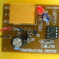
Temperature Switch
We bring forth the best Temperature Switch for our valued clients. We are a reliable Manufacturer and Supplier of Temperature Switch, operating from India. Temperature Switch automatically switches ON, when the temperature rises to about 60oC. Temperature Switch is a very simple circuit build around IC1, which is operated in monostable mode and temperature sensor diode D1. At temperature about 60oC, the sensor triggers IC1, which makes output of IC1 at high level and energizes the relay. In addition, Temperature Switch turn OFF as temperature goes below 60oC.About the Circuit : The circuit of Temperature Switch is shown in figure. Sensor Diode D1 in reverse bias is connected to trigger pin2 of IC1. At temperature below 60oC, the reverse resistance of D1 is very high, which keeps trigger pin2 of IC1 at a voltage greater than 1/3Vcc. Hence, IC1 does not get trigger, which gives low pulse at output pin3. As a result, transistor T1 is in cut off state and relay remains off. As soon as the temperature reaches to about 60oC, the reverse resistance of D1 drops to a very low value normally less than 1KW. In this case, it is considered as forward bias. As a result, voltage at pin2 goes below 1/3Vcc. Now IC1 gets triggered and output at pin3 goes to high level, which causes T1 to conduct. Relay connected to collector of T1 now becomes on. In addition, LED D4 glows which gives visual indication. The sensitivity of the circuit is adjusted with the aid of P1. The circuit requires a DC power supply of 9V to 12V. Diode D3 is used as a rectifier diode whereas capacitor C4 is used for filtering.
Type : Temperature Switches
Material : ABS, Brass
Shape : Rectengular
Certification : CE Certified
Color : Multicolor
Design : Customised
...more
Temperature Monitor
The Temperature Monitor is a miniature temperature controller device up to 100oC. This simple circuit of temperature monitor uses differential amplifier IC and temperature sensor. The three different colors of LED indications are used to indicate different temperatures. The temperature at which LEDs will glow set by preset P1. Generally LED D1 will glow at normal temperature. As the temperature increases LED D2 glows. At highest temperature LED D3 glows.About the Circuit : As described earlier circuit uses differential amplifier IC, IC1. The reference voltages are applied to pin2 and pin6, which are set by preset P2 and P3 respectively. The differential voltages developed at pin3 and pin5 according to the voltage produced by R1/P1 and temperature sensor, which gives an output voltage of 10mV/oC. Accordingly output at pin1 and pin7 changes and LED indication changes. At normal temperature, voltage produced by sensor is smaller than either of the reference potentials. The output at pin1 and pin7 are low: D1 will then light. When the ambient temperature rises, the output of sensor rises proportionally. When the level of the sensor output lies between the two reference levels, the output at pin1 is high and that of pin7 is low. Diode D2 will then light, showing that the critical temperature has been reached. At even higher temperature, the output at pin7 also goes high and D3 lights, while the other two LEDs will go out. At the same time, the relay will be energized via T1. Also LED D6 lights which gives visual indication. Zener diode D4 ensures that T1 does not come on when D2 lights. The temperature at which the LEDs should light can be set with preset P1, P2 and P3. The precaution should be taken that the monitor is intended for normal temperatures between 25oC and 100oC.
Type : Temperature Monitors
Application : Industrial Use
Color : Black, Grey
Voltage : 220V
Screen Size : 10inch, 14inch
Frequency : 50HZ, 60HZ
Memory Size : 1gb, 512mb
Feature : Durable
...more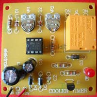
Cooler Timer Circuit
During summer seasons, we all us knows the need of coolers. If cooler is on for long time, then the requirement of water is also very large. To minimize this problem to a large extent cooler timer is designed. Cooler Timer Circuit controls the ON and OFF time of cooler water pump according to the user’s requirement. The minimum and maximum time setting is fraction of second and one-and-a-half minute respectively. Our valued clients can avail Cooler Timer in different specifications. About the Circuit :Cooler Timer is designed using popular timer IC named as IC1. The circuit facilitates time adjustment of both charged and discharged states of the relay. IC1 is used is a stable mode. When power is ON, capacitor C3 starts charging via R1/VR2/R2 and on time of pump starts. When its voltage reaches to 2/3Vcc, it starts discharging via R2/VR1/R1. Now, OFF time of pump starts and when its voltage reaches to a value less than 1/3Vcc, it starts charging again and procedure repeats again. At the output of IC1 at pin3, on and off pulses are obtained. During on time transistor T1 turns ON, relay connected at the collector terminal energizes, and in turns pump becomes on. During off pulse, T1 turns off and relay becomes off which in turn makes pump off.Separate delays for charged and discharged states of the relay are achieved by using two diodes (D1 and D2) and two preset VR1 and VR2 between pins 2 and 7 of the IC1. The preset VR1 and VR2 provide control over the ‘on’ and ‘off’ stages of the relay, respectively.Features : The circuit turns on and off with setting of ‘on’ time delay and ‘off’ time delay. Diodes D4 and D5 are used for rectification and capacitor C1 is used for filtration. Timer with ON time and OFF time setting for cooler/pump
Type : Circuit
Shape : Rectangular
Feature : Durable
Finishing : Polished
Warranty : 6 Months
...more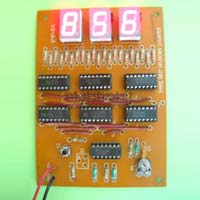
Three Digit Up Down Counter Circuit
We are offering Three Digit Up down Counter Circuit enables users to count from 0 to 999 in up as well as down mode at any instant of counting. three digit updown counter can be used for many applications such as clock generator, frequency meters etc.The circuit uses three updown counter ic1, ic2 & ic3 and three bcd to seven segment decoder ic4, ic5 & ic6. The clock’ circuit and updown switching are designed using nor gate as ic5. Three 7-segment displays in common cathode configuration are used to display the count.About the circuit :When power is switched on, the clock pulses generated by rc network build around two nor gates in ic5 is fed to the clock input (pin1) of ic1, ic2 & ic3. As a result counting starts in up or down mode depending on the logic present at updown mode pin10. If pin10 is at high level, counter starts up counting and starts down counting when it is at low level. This logic is set with the aid of logic circuit design using two nor gates in ic5 and toggle switch s1. When s1 is in up position, pin10 gives logic high and when s1 is in down position, it gives logic low. Reset switch s2 is used to reset the counter. In this case, displays show 000 in two 7- segment displays and counting starts again.At every clock pulse, count increases by one in up mode and decreases by one in down mode. The clock-out terminal (pin 7) of ic1 is connected to clock-in terminal (pin 5) of ic2. Similarly, clock-in terminal of ic2 is connected to the clock-out terminal of ic3. Thus, when ic1 completes counting from 0 to 9 in up mode or 9 to 0 in down mode, ic2 starts counting. In the similar way, ic3 counts. The display can be shown on three 7- segment displays named as dis1, dis2 and dis3.The speed of counting can be set with the aid of pot p1. The number of digits the counter provides can be extended by adding more counterdecoderdisplay stages.
Type : Circuit
Shape : Rectangular
Feature : Durable
Finishing : Polished
Warranty : 6 Months
...more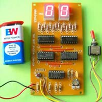
Two Digit Up Down Counter Circuit
We are offering Two Digit Up Down Counter Circuit enables users to count from 0 to 99 in up as well as down mode at any instant of counting. two digit updown counter is suitable for many applications such as clock generator, frequency meters etc. The circuit uses updown counter ic1 & ic2 and bcd to seven-segment decoder ic3 & ic4. The clock circuit and updown switching is neither designed using four nor gate ic5. Two 7-segment displays in common cathode configuration are used to display the count.About the circuit :When power is switched on, the clock pulses generated by rc network build around two nor gates in ic5 is fed to the clock input pin1 of ic1 & ic2. As a result counting starts in up or down mode depending on the logic present at updown mode pin10. If pin10 is at high level, counter starts up counting and starts down counting when it is at low level. This logic is set with two nor gates in ic5 and toggle switch s1. When s1 is in up position, pin 10 goes logic high and when s1 is in down position, it gives logic low. Reset switch s2 is used to reset the counter. In this case, displays show 00 in two 7- segment displays and counting starts again.At every clock pulse, count increases by one in up mode and decreases by one in down mode. The clock-in terminal (pin5) of ic1 is connected to clock-out terminal (pin7) of ic2. Thus when ic1 completes counting from 0 to 9 in up mode or 9 to 0 in down mode ic2 starts counting. The display can be shown on two 7- segment displays named as dis1 and dis2.The speed of counting can be set with the aid of pot p1. The number of digits the counter provides can be extended by adding more counterdecoderdisplay stages.
Type : Circuit
Shape : Rectangular
Feature : Durable
Finishing : Polished
Warranty : 6 Months
...more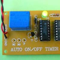
Auto On Off Timer Circuit
Auto On/Off Timer is a simple and inexpensive timer, widely used to switch on/off devices. Auto On/Off Timer has a settable timing between 3min to 30min. The circuit is built around counter IC4060 (IC1) and inverter IC4049 (IC2). The circuit switches on automatically when power is on, and it switches off when the settable time is over. About the Circuit : IC1 has on-chip oscillator whose frequency is determined by external RC network connected to pins 9, 10 and 11. When power is on, pulse at junction R4-C2 resets the counter and counting starts. The output at pin3 of IC1 is low, which is given to inverter input pin3 of IC2. This low voltage input becomes high at the output of inverter at pin2. Transistor T1 turns on and relay is energized. T1 remains on until output at pin3 of IC1 becomes high. When the counting reaches to last bit or the time is over, output at pin3 of IC1 becomes high. As a result, the pulse at pin2 of IC2 goes low and T1 turns off. At the same time relay becomes off and it remains off until pin3 of IC1 goes low again. Here LED D1 and D2 are used to give visual indication. D1 gives the indication of timing pulse generation, whereas glowing of D2 indicates timer on indication. Calibration: The time delay between 3min to 30min is set with the help of preset P1.
Type : Circuit
Shape : Rectangular
Feature : Durable
Finishing : Polished
Warranty : 6 Months
...moreBe first to Rate
Rate ThisShare your Correspondence Details to receive messages from Elektrokit