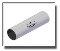
WELD ON REPAIR PIPE SLEEVE
Weld on Repair Sleeve » Carbon Steel & Stainless Steel Weld on Repair Sleeve Carbon Steel Weld on Repair Sleeve and Stainless Steel Weld on Repair Sleeve are designed to repair and reinforce in-service steel pipelines without shutdown or service disruption. Weld on Repair Sleeves are suitable for repair of weak or leaking areas caused by external/internal corrosion, damage (dents, gouges), inferior welds, defective piping material and other problematic causes.This can be furnished as full body repair sleeves or partial repair sleeves depending on the application need. Fittings are supplies standard beveled for welding (square cut sleeve ends) and welding back up strips are available. Pressure grade and Structural grade materials are available in both carbon steel and stainless steel. Weld On Repair Sleeve feature :Immediate availabilityBuilt to exact pipe diameters for custom fitMaterial grades and thickness to application codes/requirementsRestores host pipe to original & future expected service requirementsCoatings for corrosion resistance Beyond repair, Weld On SLeeves can be used to cradle, support, reinforce or pad pipelines in above ground piping systems. » Typical Application Repair, Permanent, Splits, Holes, Punctures, Corroded Areas, Inferior Welds, Gouges » Types of Damages Weld On Repair Sleeves are suitable for these types of damages.
...more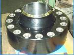
Swivel-ring Flanges
As we have been involved with the Offshore Industry almost from the start in India, we have endeavored to satisfy changing demands. To that end we commissioned an independent body to design a full range of swivel ring flanges, primarily for subsea connection of pipework, where handling for bolt alignment is facilitated. These designs, to ASME and BS5500 codes, are fully supported by corroborative calculations and accommodate the use of hydraulic bolt tensioning equipment. Hundreds of these items have been manufactured for the offshore industry over the past ten years. Most material grades and testing conditions can be accommodated. As usual with our Company a quality product and quick delivery is available. These items can also be supplied clad - for more information about swivel ring flange specifications.
...more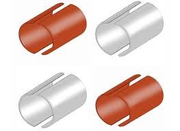
PRE STRESSED METALLIC PIPE SLEEVE
Pre Stressed Metallic Sleeve » General The pre-stressed metallic sleeves supplied are used for pipeline defects repair by the shielded metal arc welding process (SMAW). The pipelines repaired are manufactured by the Electric Resistance Welding (ERW) technique. The specification of material of construction is API 5L Gr B, X42, X46, X52, X56, X 60, X 65, X70 - PSL 1 - PSL2 (minimum yield 245000 / 52000 / 60000 / 65000 / 70000), ASTM A36 (structural; minimum yield 36,000 psi), ASTM A572 GR42, GR50, GR55, GR60, GR65 (structural; minimum yield 29,000 psi), ASTM A516 GR55, GR60, GR65, GR70 (pressure vessel; minimum yield 38,000 psi), ASTM A537 Class I, Class 2, Class 3 (pressure vessel; minimum yield 50,000 psi), EN 10025 - S235, S275, S355, S450 The pipelines nominal size is 2" NB to 60" OD and Thickness 4 mm to 100 mm. » Design & Construction The pre-stressed sleeves are of full encirclement split type and are manufactured by a production process, that minimizes occurance mill defects. Axial edges of the sleeves are bevelled to form 60° weld angle on assembly for the horizontal butt joint. A recess on the inner side of each pair of half sleeves is machined (cut out) to accommodate a 3 mm thick by 18 mm wide backing strip along the horizontal joint. The backing strips are manufactured from the same material as the sleeves and supplied. Circumferential edges of the sleeves is pre-fabricated to form 90° lap joint with the pipe.The internal diameter of the sleeves is designed and constructed so as to fit on the pipe withour leaving a gap between the inner surface of the sleeve and outer surface of the pipe all around.On assembly prior to welding, the maximum root gap shall be 3.0 mm on both horizontal joints. A 1.5 mm root face shall be allowed on both edges.Both the horizontal and circumferential edges shall have a smooth finish.The sleeve surfaces shall be protected from corrosion by a suitable method such as coating with corrosion resistant paint or other acceptable methods. » Feature Lightweight for easy handling and installation.Eliminates costly downtime.Minimizes repair costs. » Dimensions The Sleeves shall be manufactured to the standard lengths of 1.0 m and 3.0 m for any diameter of pipe.The backing strips shall be manufactured in standard lengths of 3m. » Material Material used are structural quality carbon steel or pressure vessel quality carbon steel plates, which are to ASTM specifications, and in the following grades:API 5L Gr B, X42, X46, X52, X56, X 60, X 65, X70 - PSL 1 - PSL2 (minimum yield 245000 / 52000 / 60000 / 65000 / 70000)ASTM A36 (structural; minimum yield 36,000 psi)ASTM A572 GR42, GR50, GR55, GR60, GR65 (structural; minimum yield 29,000 psi)ASTM A516 GR55, GR60, GR65, GR70 (pressure vessel; minimum yield 38,000 psi)ASTM A537 Class I, Class 2, Class 3 (pressure vessel; minimum yield 50,000 psi) EN 10025 - S235, S275, S355, S450The chemical composition does not exceed the percentages specified for the ASTM material ordered. Repair sleeves are fabricated from plate with low carbon equivalency for good weld ability.The maximum allowable carbon equivalency (CE) quality carbon steel plates will be based on the heat analysis.The maximum allowable carbon equivalency (CE) pressure vessel quality carbon steel plates will be based on the heat analysis, in most cases. Note : The sleeve can be manufactured in any grade as per the application & client requirements. » Mill Test Certificate Mill test certificate will be provided for the whole batch supplied, accordingly. » Packing The Sleeves shall be packed in wooden boxes suitable for outdoor storage. These boxes will be constructed so as to allow handling with either overhead crane or fork lift or mobile Crane.The 2 pieces comprising a pair of sleeves will be clearly marked for ease of identifaction of matching parts.Each box will be clearly marked to indicate size, length and number of complete pair of sleeves packed therein. These markings will be made by indelible ink that can withstand adverse outdoor weather effects.The sleeves will be packed seperately according to their length.An appropriate packing material shall be used to separate individual pieces so as to avoid damaging the corrosion resistant paint coating.The backing strips will be packed in fully enclosed wooden boxes. This boxes shall be constructed so as to allow opening and closing of the top side to ease the removal of strips. » Size We can manufacture Pre-stressed Metallic Sleeve for any size depending on the client's requirement.
...more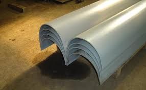
HALF REPAIR PIPE SLEEVE
Half repair Pipe Sleeve » General Half Repair pipe Sleeves are designed to avoid a costly shut down. Existing lines can be cased without thru-put loss, because it is not necessary to shut down the carrier line to perform the required repair. A full scope of sizes, ASTM grades of steel plate (structural and pressure vessel quality), wall thickness and longitudinal edge options are available. Half Sole Repair Sleeves, also called split casing or half wrap, are custom-fabricated to your specifications, to assure a precision product and secure fit. There are four types of material available, two pressure-rated steels and two structural-grade steel. The pressure-rated steel sleeves can be used to repair leaking and non-leaking defects while the structural-grade steel sleeves can function as reinforcement for a defective area. » Material Material used are structural quality carbon steel or pressure vessel quality carbon steel plates, which are to ASTM specifications, and in the following grades:API 5L Gr B, X42, X46, X52, X56, X 60, X 65, X70 - PSL 1 - PSL2 (minimum yield 245000 / 52000 / 60000 / 65000 / 70000)ASTM A36 (structural; minimum yield 36,000 psi)ASTM A572 GR42, GR50, GR55, GR60, GR65 (structural; minimum yield 29,000 psi)ASTM A516 GR55, GR60, GR65, GR70 (pressure vessel; minimum yield 38,000 psi)ASTM A537 Class I, Class 2, Class 3 (pressure vessel; minimum yield 50,000 psi) EN 10025 - S235, S275, S355, S450The chemical composition does not exceed the percentages specified for the ASTM material ordered. Repair sleeves are fabricated from plate with low carbon equivalency for good weld ability.The maximum allowable carbon equivalency (CE) quality carbon steel plates will be based on the heat analysis.The maximum allowable carbon equivalency (CE) pressure vessel quality carbon steel plates will be based on the heat analysis, in most cases. Note : The sleeve can be manufactured in any grade as per the application & client requirements. » Manufacturing Half Repair Pipe Sleeve is formed by rolling, step braking, or die forming without the use of heat treating.Longitudinal edges of the Half Sole are beveled for welding, if requested, at 30º. The bevel are a mechanical type and/or produced by plasma torch burning.Half Repair Pipe Sleeve ends have sheared square edges for fillet welding, unless square end bevel is requested, and are available in maximum lengths as per clients requirements. » Feature The steel repair sleeves can be used for internal and external corrosion, gouges, dents, grooves, arc burns, cracks, defective girth welds, laminations and leaks.Pressure containing sleeves feature a wall thickness equal to or greater than required for the maximum allowable operating pressure or the full strength of the pipe being repaired. The steel Repair sleeve material is certified and the carbon equivalent will not exceed 0.45 percent. Each half-sole segment comes with one pre-crimped back-up strip.Steel Repair Sleeves can be used as pads or cradles for above ground piping, drain tile supports and patches (segments in 90° and 180° arcs, from 6-inches to 10 feet in length are available as specials).Each Steel Repair Sleeve has standard bevels with a back-up strip and material certifications. Sleeve ends are square cut. Back-up strip are not included with Standard Girth Weld Steel Repair Sleeves but are available as special order. » Milling of Half Repair Pipe Sleeves for backing Strips Half repair pipe sleeves can be milled on the inside longitudinal edges for the backing strips. Depth of 1/16" (.625) -0" + 1/32" and width 5/8" (.625) -0 + 1/16" on each side. Outside longitudinal edges are beveled 30° (+5° - 0°) for welding. » Backing Strips Backing Strips are hot rolled commercial carbon steel sheet and strips of commercial quality. A-569 / A1011 SS GR33 / IS:2062 or equivalent in coils and cut lengths having a maximum carbon of 0.15%. 1 1/4" wide, 16 gauge (.0598) with a tolerance of min. 0.0538 - max 0.0658, 10' long, precrimped (10 degree total bend). ASTM steel composition of A569/A1011 SS GR33/IS:2062: Carbon (Max) Manganese (Max) Phosphorus (Max) Sulphur (Max) Copper (when specified) 0.15 0.60 0.036 0.035 0.20 min. » Mechanical Properties and Testing Mill test reports will be furnished on all materials. If stock plate is not available with a maximum hardness guarantee independent testing may be performed to check the hardness on stock plate and this report will be submitted along with ptoduct. If required additional testing reports will be furnished which includes destructive, magnetic particle, liquid penetrate, ultrasonic and radiographic reportrs carried out by a reputed third party. » Dimensional Requirements Longitudinal edges to be beveled to 30 degrees (+5 degrees -0 degrees), with a root face (land of 1/16" (+-1/32"). Inside diameter (I.D.) of each Half pipe repair sleeve will be fabricated to match the outside diameter (O.D.) of Standard nominal line pipe (bare with tolerance of: Half repair sleeves can be manufactures in such a way that when two (2) halves of the sleeve are placed on the pipe, their total circumference shall equal the circumference of the pipe minus a gap between the longitudinal edges on either side of 1/16" (-1/16" + 1/32") for welding. » Size We can manufacture in any size and also as per client's requirement.
...more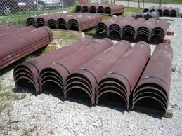
HALF PIPE SLEEVE
Half Pipe Sleeve » General Half Repair pipe Sleeves are designed to avoid a costly shut down. Existing lines can be cased without thru-put loss, because it is not necessary to shut down the carrier line to perform the required repair. A full scope of sizes, ASTM grades of steel plate (structural and pressure vessel quality), wall thickness and longitudinal edge options are available. Half Sole Repair Sleeves, also called split casing or half wrap, are custom-fabricated to your specifications, to assure a precision product and secure fit. There are four types of material available, two pressure-rated steels and two structural-grade steel. The pressure-rated steel sleeves can be used to repair leaking and non-leaking defects while the structural-grade steel sleeves can function as reinforcement for a defective area. » Feature The steel repair sleeves can be used for internal and external corrosion, gouges, dents, grooves, arc burns, cracks, defective girth welds, laminations and leaks.Pressure containing sleeves feature a wall thickness equal to or greater than required for the maximum allowable operating pressure or the full strength of the pipe being repaired. The steel Repair sleeve material is certified and the carbon equivalent will not exceed 0.45 percent. Each half-sole segment comes with one pre-crimped back-up strip.Steel Repair Sleeves can be used as pads or cradles for above ground piping, drain tile supports and patches (segments in 90° and 180° arcs, from 6-inches to 10 feet in length are available as specials).Each Steel Repair Sleeve has standard bevels with a back-up strip and material certifications. Sleeve ends are square cut. Back-up strip are not included with Standard Girth Weld Steel Repair Sleeves but are available as special order. » Material Material used are structural quality carbon steel or pressure vessel quality carbon steel plates, which are to ASTM specifications, and in the following grades:API 5L Gr B, X42, X46, X52, X56, X 60, X 65, X70 - PSL 1 - PSL2 (minimum yield 245000 / 52000 / 60000 / 65000 / 70000)ASTM A36 (structural; minimum yield 36,000 psi)ASTM A572 GR42, GR50, GR55, GR60, GR65 (structural; minimum yield 29,000 psi)ASTM A516 GR55, GR60, GR65, GR70 (pressure vessel; minimum yield 38,000 psi)ASTM A537 Class I, Class 2, Class 3 (pressure vessel; minimum yield 50,000 psi) EN 10025 - S235, S275, S355, S450The chemical composition does not exceed the percentages specified for the ASTM material ordered. Repair sleeves are fabricated from plate with low carbon equivalency for good weld ability.The maximum allowable carbon equivalency (CE) quality carbon steel plates will be based on the heat analysis.The maximum allowable carbon equivalency (CE) pressure vessel quality carbon steel plates will be based on the heat analysis, in most cases. Note : The sleeve can be manufactured in any grade as per the application & client requirements. » Manufacturing Half Repair Pipe Sleeve is formed by rolling, step braking, or die forming without the use of heat treating.Longitudinal edges of the Half Sole are beveled for welding, if requested, at 30º. The bevel are a mechanical type and/or produced by plasma torch burning.Half Repair Pipe Sleeve ends have sheared square edges for fillet welding, unless square end bevel is requested, and are available in maximum lengths as per clients requirements. » Size We can manufacture half pipe sleeve in any size as per client's requirement.
...more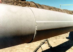
FULL ENCIRCLEMENT STEEL PIPE SLEEVE
Full Encirclement Steel Sleeve Full-encirclement steel sleeves have historically been a widely used method for general repair of defects in onshore pipelines. Because they involve welding, they are generally not applicable to the repair of defects in offshore pipelines. In the early 1970s, the American Gas Association funded a major project on the effectiveness of various repair methods with emphasis on full-encirclement sleeves. The results of this work showed that a properly fabricated steel sleeve restores the strength of a defective piece of pipe to at least 100% of SMYS. The keys to properly fabricating a sleeve are the use of a proven procedure and skilled personnel. Most of the previous research on steel repair sleeves has addressed only their response to static pressures and lateral loads. Their response to repeated pressure cycles has not been studied in depth. Pressure-cycle fatigue tests were performed as part of an in-depth evaluation of steel compression sleeves. When they are used to repair defects in pipelines subjected to significant cyclic pressurization, steel sleeves are likely to have a finite time to failure. In the case of a reinforcing sleeve, the useful life might be controlled by the repaired defect, whereas in the case of a pressure-containing sleeve, the sleeve itself would be the critical component. Whenever a steel sleeve is to be used in cyclic service, its fatigue resistance should be evaluated. The results of the fatigue evaluation should be used to establish a suitable limit on the allowed service life before replacement is required. Type A Sleeves (Reinforcing) The Type A sleeve is particularly attractive because it can be installed on a pipeline without welding it to the carrier pipe. Such a sleeve provides reinforcement for the defective area. It cannot contain pressure and is used only for nonleaking defects. It should be installed at a pressure level below that at which the area of the line pipe with the defect might be expected to fail. A typical configuration and weld details for a Type A sleeve are shown in Figures 1 and 2, respectively. The sleeve consists of two halves of a cylinder of pipe or two appropriately curved pieces of plate that are placed around the carrier pipe at the damaged area and after positioning, are joined by welding the side seams. As shown in Figure 2, the seams may be single-V butt welds or overlapping steel strips fillet welded to both halves may join the sleeve halves. If the side seams are to be butt welded and the sleeve halves are to be made from the same diameter pipe as the carrier pipe, then each half should actually be more than half of the circumference of the piece of pipe. Otherwise, the gap to be filled by butt-welding will be too large. With the overlapping strip concept, it is not essential that each half actually be more than half of the circumference because the gap can be easily bridged. One major advantage of a Type A sleeve over other types of repairs is that for relatively short flaws it can function effectively without itself necessarily being a high-integrity structural member. Relatively short flaws are those whose length (L) are less than or equal to , where D is pipe diameter, t is pipe wall thickness, and all dimensions are in consistent units. For such flaws, the sleeve’s role is limited to restraining bulging of the defective area. As a result, it can be fabricated simply and requires no rigorous nondestructive inspection to ensure its effectiveness. Also, because the sleeve does not carry much hoop stress in the case of short flaws, it can fulfill its restraining role without necessarily being as thick as the carrier pipe. As a rule of thumb, the thickness of the sleeve should not be less than two-thirds of the thickness of the carrier pipe when used to repair short flaws, assuming that the sleeve is at least as strong as the carrier pipe. It is common to simply match the grade and wall thickness of the carrier pipe. With flaws longer than , the sleeve thickness should be at least as great as that of the carrier pipe, again assuming that the sleeve is at least as strong as the carrier pipe. It is permissible to use sleeves thinner than the carrier pipe if their strength is increased by an amount sufficient to compensate for their thickness being less than that of the carrier pipe. In a similar fashion, the sleeve could be of an acceptable material with lower strength than that of the carrier pipe if its thickness is increased to compensate for the difference is strength. To assure that adequate restraint exists and that the sleeve will indeed prevent a rupture, the sleeve should be extended onto sound, full-thickness pipe at least 50 mm (2 inches) beyond the ends of the defect. The operator should design the repair to carry anticipated loads. The Type A sleeve has some minor disadvantages. It is not useful for circumferentially oriented defects because it has no effect on the longitudinal stress in the carrier pipe. Secondly, it cannot be used to repair leaking defects. Thirdly, it creates a potential crevice in the form of an annular space between it and the carrier pipe that may be difficult to protect from corrosion. However, there have been no reported service failures caused by this potential problem. Because of this potential problem, however, some companies use full-encirclement sleeves as Type A sleeves, but weld the ends to the pipe to prevent further corrosion, thus making them essentially Type B sleeves. Assuring Effective Reinforcement To be effective, the Type A sleeve should reinforce the defective area, restraining it from bulging radially as much as possible. First and foremost, the sleeve should be installed with a minimal gap between the sleeve and the carrier pipe in the area of the anomaly. Forming and/or positioning the sleeve so that it firmly contacts the carrier pipe, especially at the area of the defect, can assure that the gap is minimized. One or more of the following actions (discussed separately in this sub-section) can further enhance the effectiveness of a Type A sleeve: • Reduce pressure in the carrier pipe during sleeve installation. • Externally load the sleeve to force it to fit tightly against the carrier pipe. • Use a semi-liquid material that will fill and harden in any gaps in the annular space between the sleeve and the carrier pipe. • Apply special fit-up procedures for seam welds. • Use special epoxy-filled shells. Pressure Reduction Pressure reduction is essential if the defect being repaired is at or near its predicted failure pressure at the start of the repair operation. If the pressure is not reduced in such a case, the repaired defect could begin leaking after the sleeve is installed. In contrast, when the pressure is reduced, the radial bulging at the defect location is reduced and can be prevented from recurring during re-pressurization by using a tightly fitting sleeve. Research results(19)(20) indicate that a pressure reduction of 33-1/3% from the predicted failure pressure was adequate for the application of Type A sleeves. Typically, a pressure reduction is not necessary if it can be shown that the defect is not at or near its predicted failure pressure. For example, if calculations based on the size of the defect show that its predicted failure pressure is 33-1/3% or more above the current pressure, a Type A sleeve can effectively repair it without a reduction in pressure. Reinforcing sleeves usually do not share much of the hoop stress that is acting on the carrier pipe unless special application techniques are used. Even if the sleeve fits perfectly and has 100%-efficient side seams, it will at most carry one-half of the hoop stress recovered after a pressure reduction if its wall thickness is that same as that of the carrier pipe. The optimum amounts of stress sharing produced by a snugly fitting sleeve for various amounts of pressure reduction are illustrated in Figure 3. The notation used in Figure 3 is as follows: ta = actual wall thickness of carrier pipe ts = wall thickness of steel sleeve So = initial hoop stress in carrier pipe Sr = reduced hoop stress in carrier pipe after installation of steel sleeve Pr = reduced pressure at time sleeve is applied Ph = highest pressure previously experienced by the carrier pipe after defect was present. SMYSc = specified minimum yield strength of carrier pipe. SMYSS = specified minimum yield strength of sleeve. The actual amount of hoop stress supported by the sleeves is usually much less than indicated on the graph due to variations in fit and efficiency of side seams. In spite of this, a properly fabricated sleeve can restore the strength of a defective piece of pipe to at least 100% of SMYS. Figure 3. Theoretical relationships between carrier pipe stress, repair pressure, and wall thickness Figure 4 shows predicted amounts of stress sharing for various degrees of less than optimum fit-up with a sleeve of the same wall thickness as the carrier pipe. The degree of fit-up was modeled using a load transfer coefficient as follows: • 1.0 for ideal case of perfect fit-up, which is never approached in practice without mechanical loading • 0.50 for a strong highly compressed epoxy filler, such as that used in tight-fitting compression sleeves (see Section 3.3.2.6) • 0.25 for typical tight-fitting sleeve with epoxy filler • 0.15 for typical tight-fitting sleeve with epoxy filler only in the defect area One can see that there is much less transfer of hoop stress to the sleeve in the realistic cases than in the ideal case. Since the main function of sleeves is to prevent radial bulging at the defect, it is not necessary for them to carry much stress. However, they should fit snugly to restrain bulging. Sleeves used to repair long defects (i.e., L ≥, should be capable of sustaining a significant amount of hoop stress and are expected to absorb an appreciable amount of hoop stress. The reason is that a long defect-weakened region will not be able to distribute hoop stress to the areas of the carrier pipe beyond the ends of the defect. Instead, the region will tend to yield plastically and transfer circumferential stress to the sleeve. Figure 4. Predicted relationships between carrier pipe stress, repair pressure, and degree of fit-up (transfer coefficient). Mechanical Loading The two halves of a sleeve can be forced to conform to the carrier pipe and their sides can be drawn together appropriately for welding by mechanical means such as those shown in Figure 5. These can consist of chains and jacks (Figure 5b) or special preloading devices (Figure 5c). Lugs can be pre-installed on each half (Figure 5a). At the option of the installer, the lugs can be cut off after installation or left in place. Cutting them off facilitates coating the sleeve, an important consideration. A third option is the special chain-clamp device shown in Figure 5c. The hydraulic actuator that accompanies this latter device can be used to produce a significant preload in the sleeve. A significant preload can enhance the effectiveness of a Type A sleeve in the same manner as a pressure reduction in the carrier pipe. However, preload should not be substituted for pressure reduction in cases where a reduction of pressure is necessary for safety prior to the start of repair operations. Figure 5. Mechanical methods for assuring tight-fitting Type A sleeves Hardenable Fillers Hardenable fillers, such as epoxy or polyester compounds, are frequently used to ensure that no gaps exist between the sleeve and the carrier pipe. These compounds are typically mixed and trowelled into depressions in the carrier pipe, such as dents and pits. After the mixture hardens, the filler is shaped using files or other similar tools until the outside diameter of the pipe is restored. Another alternative is described below. Before the mixture hardens, the sleeve halves are placed around the pipe, and mechanical means, such as those described above, are used to squeeze the excess filler material. By the time the side seams of the sleeve have been welded, the filler mixture has usually solidified and load transfer between the sleeve and the carrier pipe is assured at all defect locations. Tests performed on pipe sections with filled gouges and dents(19)(20) showed that such fillers are very effective. Fit-Up on Submerged-Arc-Welded and Flash-Welded Line Pipe One concern with respect to applying Type A sleeves is the presence of a crown or reinforcement on the seam weld of submerged-arc-welded (SAW) carrier pipe or the flash on flash-welded carrier pipe. To assure a tight-fitting sleeve, three options are available. The first option is to remove the weld crown or flash by grinding it flush to the surface of the carrier pipe. This option is acceptable if the pressure has been reduced as suggested in Section 3.3.2.1. The second option is to grind a compensating groove in one of the sleeve halves. If this second option is selected, it may be desirable or necessary (in the case of long defects) to use a sleeve that is thicker than the carrier pipe by an amount that compensates for the thickness of material removed, including any compensation needed for differences in material strength. The third option is to force the unmodified sleeve over the weld reinforcement after sufficient filler material has been deposited to fill the expected gaps. This third option is acceptable if the resulting fit-up of the sleeve halves is adequate for side-seam fabrication. With the standardmethod of application shown in Figure 5b, there is no risk of damaging the weld. This third option should not be used with relatively high-force methods, such as lug and bolt (Figure 5a) or chain clamp (Figure 5c), as local bending adjacent to the seam weld reinforcement may result. Epoxy-Filled Shells British Gas developed a variation of the filled-sleeve concept in the form of their epoxy-filled shell repair method.(25) In this case, the shell is a sleeve with a standoff distance of several millimeters from the carrier pipe. The shell is placed on the defective pipe, and bolts are used to center it. The side seams are then welded, and the gaps at the ends are sealed with trowelled filler. After these seals have hardened, epoxy is pumped into the annular space until it comes out an overflow hole at the top of the sleeve. Once the epoxy filler has hardened, the radial bulging tendency of the defect is restrained by the epoxy in the same manner as a conventional Type A sleeve would have if it were directly in contact with the sleeve. Data have been presented(26) that show that the epoxy-filled shell also can be used to repair weakened, but not leaking, girth welds. Bonding between the epoxy and the sleeve and the epoxy and the pipe permits the transfer of longitudinal stress. If the sleeves are used for an under-water repair, an epoxy that cures properly in water should be used. Steel Compression Sleeves Steel compression sleeves are a special class of Type A sleeves. They are designed, fabricated, and applied so that the repaired section of the carrier pipe is maintained under compressive hoop stress during subsequent operation. This approach is attractive for repairing longitudinally oriented crack-like defects because without a tensile hoop stress there is no driving force for crack growth. This type of sleeve is not suitable for the repair of circumferential cracks or for defects in field bends. CSA Z662(10) addresses the use of steel compression sleeves.fSteel compression sleeves involve installing two sleeve halves over the defect area and drawing them together using clamps, jacks and chains, or lugs and bolts. The sleeve halves are then welded together using conventional welding techniques. Pressure reduction during installation is normally used to induce compression in the carrier pipe. Thermal contraction of the longitudinal seam welds also promotes compression in the carrier pipe. Epoxy filler is used between the carrier pipe and sleeve to achieve the transfer of stresses. As pointed out previously, pressure reduction alone will only transfer a portion of the hoop stress from the carrier pipe to the sleeve. Half Pipe Sleeve is a commercial product that was developed to combine pressure reduction with thermal shrinkage of the sleeve for achieving full compression in the carrier pipe. Figure 6 illustrates the installation process for Half Pipe Sleeve. Two steel sleeve halves with sidebars are installed over the defect, the sleeve halves are heated, and are initially held in place with chain clamps or hydraulic jacks. The halves are then welded together using two longitudinal sidebars. During installation, an epoxy layer is applied between the sleeve and the carrier pipe. The epoxy is used as a lubricant when the halves are placed on the carrier pipe and later acts as a filler to evenly transfer the load between the sleeve and the pipe. As with other versions of Type A sleeves, no welds are made to the carrier pipe. Thermal shrinkage of the sleeve upon cooling helps induce a compressive stress into the carrier pipe.(23) A completed PetroSleeve installation is shown in Figure 7. Several factors influence the degree of stress reduction in the carrier pipe. These include the fit of the sleeve, the pipe wall thickness and diameter, the sleeve wall thickness, the internal pressure during installation, and the installation temperature. Specially developed software can be used to determine the target sleeve installation temperature and to help confirm that the desired amount of sleeve compression has been achieved.(27) Quality control procedures for Half Pipe Sleeve involve monitoring sleeve temperature during the heating process and verification of the achieved carrier pipe compression by measuring how far the two sleeve halves advance towards each other using caliper measurements. Three sets of measurements on each side of the sleeve are typically made. Nondestructive inspection of the completed welds is conducted after cooling.
...more
Alloy Steel Seamless Pipes
Alloy Steel Seamless Tubes
Angle Bar
Angle Channel
Carbon Steel Pipes
Carbon Steel Tubes
coil sheet plates
Industrial Flanges
Industrial Olets
nut fasteners
Pipes Fittings
Special Steel
Stainless Steel Seamless Pipes
Stainless Steel Seamless Tubes
Be first to Rate
Rate ThisOpening Hours
Share your Correspondence Details to receive messages from Reliable Pipes & Tubes Ltd