AH rating180 Ah to 280 Ah @ C20 for 6V
28 Ah to 300 Ah @ C20 for 12V
Applicable Operating Temperature Range-40ËC (-104ËF) to +60ËC (+140ËF)
Ideal Operating Temperature Range+20ËC (+68ËF) to +25ËC (+77ËF)
Storage time from a fully charged condition12 months @ +20ËC (+68ËF). At higher temperatures, the time interval is shorter.
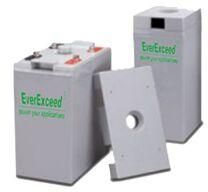
Tubular OPzS Eco flooded lead acid batteries are distinguished by their economical design, lead selenium tubular plate design, and their high tolerance to cycling. They provide the best possible compromise in lead acid plate technology. They can be used for general purpose applications, but can also be used for solar/wind and other deep discharge applications.
Salient Features
Robust tubular +ve plates consisting of a low-antimony lead selenium alloy
Microporous, corrugated, and robust separators for electrical separation of the +ve and –ve plates, optimized for low internal resistance
Very high operational reliability in rough operating conditions
Low maintenance due to reduced antimony in the alloy and high electrolyte reserve
Flame retardant ceramic plugs that filter out any drops of electrolyte from the escaping gases preventing any errant spark or flame from entering the battery
Low gassing due to PbSbSnSe alloy (en 50272-2)
SeparatorHighly porous glass micro-fibre separator, optimized for low internal resistance, for maximum absorption of the electrolyte, and for electrical separation
ContainerStandard: Reinforced ABS (UL94HB) container and cover
Optional: Flame-retardant reinforced ABS container and cover compliant with U.L.94 V-0 with an oxygen limiting index of more than 28%
Salient Features
Thick positive plate design and high Tin alloy which gives a 10-year design life @ 25°C
Advanced Pb-Ca-Tin alloy which reduces grid corrosion and increases battery life
Operation at a low internal pressure
Heavy duty insert copper terminals for ease of assembly, reduced maintenance, and increase safety
Over-sized, through-the-partition inter-cell welds which provide low resistance connections, with minimal power loss
Flame-arresting, low-pressure safety release venting system for individual cells, recognized as per U.L.924
Multi-cell design for ease of installation and maintenance
A – The terminal voltage for “ST-6” models is 6V, while that for “ST-12” models is 12V.
B – Ah rating is measured @ 25°C with end voltage per cell (EVPC) = 1.80V. The actual battery performance may be ±5% of the figures shown above.
C – SCC means Short Circuit Current and its unit is Amperes.
D – IR means Internal Resistance and its unit is milli-ohms.
E – TT means Terminal Type.
F – Actual dimensions may vary by ±1%.
Float Voltage
Float Voltage Range
:
2.25 to 2.30 VPC @ 25°C
Recommended Float Voltage
:
2.27 VPC @ 25°C
Equalize Voltage
:
2.35 VPC for 12 hours
Charging Instructions
Constant voltage charging is recommended.
Temperature compensation to be applied for temperatures ranging from 0°C to 40°C is as follows: subtract 3mV / °C / cell above 25°C (add 3mV / °C / cell below 25°C).
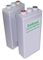
Ah Rating50Ah to 4000Ah C10. Ah rating is @25°C, with end voltage per cell (EVPC) = 1.80V.
TechnologyValve Regulated Lead Acid (VRLA) with sulphuric acid thixotropic gel (specific gravity = 1.28) as separator
+ve PlateFlat pasted grid, made of Pb-Ca-Tin-Al alloy, optimized for high corrosion resistance
-ve PlateFlat pasted grid, made of Pb-Ca-Tin-Al alloy, optimized for high corrosion resistance
ElectrolyteDilute sulfuric acid
SeparatorMicro porous and robust, for electrical separation of the +ve and -ve plates, and optimized for low internal resistance
ContainerStandard: Reinforced ABS (UL94HB) container and cover
Optional: Flame-retardant reinforced ABS container and cover compliant with U.L.94 V-0 with an oxygen limiting index of more than 28%
Salient Features
Advanced Pb-Ca-Tnalloy which reduces grid corrosion and increases battery life
Thick +ve plate technology for maximum service float life and a design life of 18 years @ 20°C
Separator manufactured using the latest German technology
Base material is a microporousduroplastic exhibiting excellent high temperature stability and mechanical strength, resulting in very good resistance to vibration and mechanical shock
Silver plated integral copper insert
Operation at a low internal pressure
Flame-arresting, low-pressure safety release venting system for individual cells, recognized as per U.L.924
Cenergy MaxPower » Energy Storage & Solar Products » Energy Storage Products » VRLA Batteries » VRLA Gel Batteries » Modular VRLA Gel Battery
Modular VRLA Gel Battery
Brochure
Download the brochure for this product.
FAQs
Read the FAQs related to this product.
Contact Sales
Contact the sales team to buy this product.
Overview
Voltage
2V
Ah Rating
50Ah to 4000Ah C10. Ah rating is @25°C, with end voltage per cell (EVPC) = 1.80V.
Technology
Valve Regulated Lead Acid (VRLA) with sulphuric acid thixotropic gel (specific gravity = 1.28) as separator
+ve Plate
Flat pasted grid, made of Pb-Ca-Tin-Al alloy, optimized for high corrosion resistance
-ve Plate
Flat pasted grid, made of Pb-Ca-Tin-Al alloy, optimized for high corrosion resistance
Electrolyte
Dilute sulfuric acid
Separator
Micro porous and robust, for electrical separation of the +ve and -ve plates, and optimized for low internal resistance
Container
Standard: Reinforced ABS (UL94HB) container and cover
Optional: Flame-retardant reinforced ABS container and cover compliant with U.L.94 V-0 with an oxygen limiting index of more than 28%
Salient Features
Advanced Pb-Ca-Tnalloy which reduces grid corrosion and increases battery life
Thick +ve plate technology for maximum service float life and a design life of 18 years @ 20°C
Separator manufactured using the latest German technology
Base material is a microporousduroplastic exhibiting excellent high temperature stability and mechanical strength, resulting in very good resistance to vibration and mechanical shock
Silver plated integral copper insert
Operation at a low internal pressure
Flame-arresting, low-pressure safety release venting system for individual cells, recognized as per U.L.924
Product Specifications
ModelA
Ah RatingB
SCCC
IRD
TTE
DimensionsF (mm/inch)
Weight
C5
C10
C24
C48
C100
Length
Width
Height
Kg (lb)
2-50
42
50
56
58
62
420
2.10
ST1
161 (6.34)
50 (1.97)
172 (6.78)
4.5 (9.9)
2-100
84
100
111
115
123
890
2.00
ST1
171 (6.74)
72 (2.83)
211 (8.31)
8 (17.6)
2-120
101
120
134
138
148
150
1.80
ST1
171 (6.74)
72 (2.83)
211 (8.31)
9 (19.8)
2-150
126
150
167
172
185
1280
1.50
ST1
171 (6.74)
102 (4.02)
211 (8.31)
11 (24.3)
2-200
168
200
223
230
246
1320
0.50
ST2
171 (6.74)
106 (4.18)
336 (13.2)
15 (33.1)
2-250
210
250
278
288
308
1660
0.45
ST2
171 (6.74)
106 (4.18)
336 (13.2)
18 (39.7)
2-300
252
300
336
345
369
1990
0.40
ST2
171 (6.74)
151 (5.95)
336 (13.2)
21 (46.2)
2-400
336
400
446
460
500
2660
0.36
ST2
210 (8.27)
173 (6.82)
336 (13.2)
28 (61.7)
2-500
420
500
559
576
615
3320
0.30
ST2
241 (9.50)
171 (6.74)
336 (13.2)
33 (72.8)
2-600
505
600
672
691
738
3980
0.28
ST2
302 (11.9)
175 (6.90)
336 (13.2)
42 (92.6)
2-700
590
660
720
806
861
4850
0.22
ST2
302 (11.9)
175 (6.90)
336 (13.2)
50 (110)
2-800
670
800
890
922
984
5300
0.20
ST2
410 (16.2)
175 (6.90)
336 (13.2)
57 (126)
2-1000
840
1000
1114
1152
1230
6550
0.16
ST2
482 (19.0)
175 (6.90)
336 (13.2)
66 (146)
2-1250
1052
1250
1393
1440
1542
8200
0.13
ST2
482 (19.0)
175 (6.90)
336 (13.2)
70 (154)
2-1500
1260
1500
1670
1723
1850
9920
0.11
ST2
400 (15.8)
350 (13.8)
351 (13.8)
100 (220)
2-1800
1510
1800
2004
2069
2220
12300
0.10
ST2
490 (19.3)
350 (13.8)
351 (13.8)
120 (265)
2-2000
1680
2000
2227
2299
2460
13400
0.09
ST2
490 (19.3)
350 (13.8)
351 (13.8)
132 (291)
2-2500
2100
2500
2784
2875
3080
16540
0.08
ST2
490 (19.3)
350 (13.8)
351 (13.8)
175 (386)
2-3000
2520
3000
3336
3451
3690
19980
0.08
ST2
710 (27.2)
350 (13.8)
351 (13.8)
210 (463)
2-4000
3360
4000
4464
4598
4920
27500
0.06
ST2
710 (27.2)
350 (13.8)
351 (13.8)
261 (576)
A – The terminal voltage for all models is 2V.
B – Ah rating is measured @ 25°C with end voltage per cell (EVPC) = 1.80V. The actual battery performance may be ±5% of the figures shown above.
C – SCC means Short Circuit Current and its unit is Amperes.
D – IR means Internal Resistance and its unit is milli-ohms.
E – TT means Terminal Type.
F – Actual dimensions may vary by ±1%.
Salient Features
Advanced Pb-Ca-Tnalloy which reduces grid corrosion and increases battery life
Thick +ve plate technology for maximum service float life and a design life of 18 years @ 20°C
Separator manufactured using the latest German technology
Base material is a microporousduroplastic exhibiting excellent high temperature stability and mechanical strength, resulting in very good resistance to vibration and mechanical shock
Silver plated integral copper insert
Operation at a low internal pressure
Flame-arresting, low-pressure safety release venting system for individual cells, recognized as per U.L.924
Cenergy MaxPower » Energy Storage & Solar Products » Energy Storage Products » VRLA Batteries » VRLA Gel Batteries » Modular VRLA Gel Battery
Modular VRLA Gel Battery
Brochure
Download the brochure for this product.
FAQs
Read the FAQs related to this product.
Contact Sales
Contact the sales team to buy this product.
Overview
Voltage
2V
Ah Rating
50Ah to 4000Ah C10. Ah rating is @25°C, with end voltage per cell (EVPC) = 1.80V.
Technology
Valve Regulated Lead Acid (VRLA) with sulphuric acid thixotropic gel (specific gravity = 1.28) as separator
+ve Plate
Flat pasted grid, made of Pb-Ca-Tin-Al alloy, optimized for high corrosion resistance
-ve Plate
Flat pasted grid, made of Pb-Ca-Tin-Al alloy, optimized for high corrosion resistance
Electrolyte
Dilute sulfuric acid
Separator
Micro porous and robust, for electrical separation of the +ve and -ve plates, and optimized for low internal resistance
Container
Standard: Reinforced ABS (UL94HB) container and cover
Optional: Flame-retardant reinforced ABS container and cover compliant with U.L.94 V-0 with an oxygen limiting index of more than 28%
Salient Features
Advanced Pb-Ca-Tnalloy which reduces grid corrosion and increases battery life
Thick +ve plate technology for maximum service float life and a design life of 18 years @ 20°C
Separator manufactured using the latest German technology
Base material is a microporousduroplastic exhibiting excellent high temperature stability and mechanical strength, resulting in very good resistance to vibration and mechanical shock
Silver plated integral copper insert
Operation at a low internal pressure
Flame-arresting, low-pressure safety release venting system for individual cells, recognized as per U.L.924
Product Specifications
ModelA
Ah RatingB
SCCC
IRD
TTE
DimensionsF (mm/inch)
Weight
C5
C10
C24
C48
C100
Length
Width
Height
Kg (lb)
2-50
42
50
56
58
62
420
2.10
ST1
161 (6.34)
50 (1.97)
172 (6.78)
4.5 (9.9)
2-100
84
100
111
115
123
890
2.00
ST1
171 (6.74)
72 (2.83)
211 (8.31)
8 (17.6)
2-120
101
120
134
138
148
150
1.80
ST1
171 (6.74)
72 (2.83)
211 (8.31)
9 (19.8)
2-150
126
150
167
172
185
1280
1.50
ST1
171 (6.74)
102 (4.02)
211 (8.31)
11 (24.3)
2-200
168
200
223
230
246
1320
0.50
ST2
171 (6.74)
106 (4.18)
336 (13.2)
15 (33.1)
2-250
210
250
278
288
308
1660
0.45
ST2
171 (6.74)
106 (4.18)
336 (13.2)
18 (39.7)
2-300
252
300
336
345
369
1990
0.40
ST2
171 (6.74)
151 (5.95)
336 (13.2)
21 (46.2)
2-400
336
400
446
460
500
2660
0.36
ST2
210 (8.27)
173 (6.82)
336 (13.2)
28 (61.7)
2-500
420
500
559
576
615
3320
0.30
ST2
241 (9.50)
171 (6.74)
336 (13.2)
33 (72.8)
2-600
505
600
672
691
738
3980
0.28
ST2
302 (11.9)
175 (6.90)
336 (13.2)
42 (92.6)
2-700
590
660
720
806
861
4850
0.22
ST2
302 (11.9)
175 (6.90)
336 (13.2)
50 (110)
2-800
670
800
890
922
984
5300
0.20
ST2
410 (16.2)
175 (6.90)
336 (13.2)
57 (126)
2-1000
840
1000
1114
1152
1230
6550
0.16
ST2
482 (19.0)
175 (6.90)
336 (13.2)
66 (146)
2-1250
1052
1250
1393
1440
1542
8200
0.13
ST2
482 (19.0)
175 (6.90)
336 (13.2)
70 (154)
2-1500
1260
1500
1670
1723
1850
9920
0.11
ST2
400 (15.8)
350 (13.8)
351 (13.8)
100 (220)
2-1800
1510
1800
2004
2069
2220
12300
0.10
ST2
490 (19.3)
350 (13.8)
351 (13.8)
120 (265)
2-2000
1680
2000
2227
2299
2460
13400
0.09
ST2
490 (19.3)
350 (13.8)
351 (13.8)
132 (291)
2-2500
2100
2500
2784
2875
3080
16540
0.08
ST2
490 (19.3)
350 (13.8)
351 (13.8)
175 (386)
2-3000
2520
3000
3336
3451
3690
19980
0.08
ST2
710 (27.2)
350 (13.8)
351 (13.8)
210 (463)
2-4000
3360
4000
4464
4598
4920
27500
0.06
ST2
710 (27.2)
350 (13.8)
351 (13.8)
261 (576)
A – The terminal voltage for all models is 2V.
B – Ah rating is measured @ 25°C with end voltage per cell (EVPC) = 1.80V. The actual battery performance may be ±5% of the figures shown above.
C – SCC means Short Circuit Current and its unit is Amperes.
D – IR means Internal Resistance and its unit is milli-ohms.
E – TT means Terminal Type.
F – Actual dimensions may vary by ±1%.
SeparatorMicro porous glass fibre, which is mechanically strong, has low electrical resistance, and absorbs the electrolyte completely into its structure
ContainerStandard: Reinforced ABS (UL94HB) container and cover
Optional: Flame-retardant reinforced ABS container and cover compliant with U.L.94 V-0 with an oxygen limiting index of more than 28%
Salient Features
Super thick +ve plates minimize corrosion and prolong life
Balanced lead-calcium -ve plates optimize recombination efficiency
Thermally welded case-to-cover bond for eliminating leakage
Single-piece container construction
Lead casting terminal, threaded copper insert with large surface area to provide maximum conductivity
Welded/epoxy, dual post sealed design provides the highest integrity seal in the industry
Large copper post design also enhances the high rate performance
Ring burn with secondary epoxy resin seal is 100% water bath tested in the factory and proven in service
Flame-arresting, low-pressure safety release venting system for individual cells, recognized as per U.L.924
A – The terminal voltage for all models is 2V.
B – Ah rating is measured @ 25°C with end voltage per cell (EVPC) = 1.75V. The actual battery performance may be ±5% of the figures shown above.
C – SCC means Short Circuit Current and its unit is Amperes.
D – IR means Internal Resistance and its unit is milli-ohms.
E – TT means Terminal Type.
F – Actual dimensions may vary by ±1%.
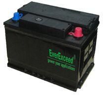
Ah RatingFor 6V:75Ah to 250Ah C20.For 12V:7Ah to 300Ah C20. Ah rating is @25°C, with end voltage per cell (EVPC) = 1.8V.
TechnologyValve Regulated Lead Acid (VRLA) with high-compression Absorbed Glass Mat (AGM) as separator
+ve PlateFlat pasted grid, made of Pb-Ca-Tin-Al alloy, optimized for high corrosion resistance
-ve PlateFlat pasted grid, made of Pb-Ca-Tin-Al alloy, optimized for high corrosion resistance
ElectrolyteDilute sulfuric acid
SeparatorHighly porous glass micro-fibre separator, optimized for low internal resistance, for maximum absorption of the electrolyte, and for electrical separation
ContainerStandard: Reinforced ABS (UL94HB) container and cover
Optional: Flame-retardant reinforced ABS container and cover compliant with U.L.94 V-0 with an oxygen limiting index of more than 28%
Salient Features
Thick positive plate design and high Tin alloy which gives a 12-year design life @ 20°C
Advanced lead tin calcium alloy which reduces grid corrosion and increases battery life
Operation at a low internal pressure
Heavy duty insert copper terminals for ease of assembly, reduced maintenance, and increase safety
Over-sized, through-the-partition inter-cell welds which provide low resistance connections, with minimal power loss
Flame-arresting, low-pressure safety release venting system for individual cells, recognized as per U.L.924
Multi-cell design for ease of installation and maintenance
A – The terminal voltage for “DP-6” models is 6V, while that for “DP-12” models is 12V.
B – Ah rating is measured @ 25°C with end voltage per cell (EVPC) = 1.75V. The actual battery performance may be ±5% of the figures shown above.
C – SCC means Short Circuit Current and its unit is Amperes.
D – IR means Internal Resistance and its unit is milli-ohms.
E – TT means Terminal Type.
F – Actual dimensions may vary by ±1%.
Float Voltage
Float Voltage Range
:
2.25 to 2.30 VPC @ 25°C
Recommended Float Voltage
:
2.27 VPC @ 25°C
Equalize Voltage
:
2.35 VPC for 12 hours
Charging Instructions
Constant voltage charging is recommended.
Temperature compensation to be applied for temperatures ranging from 0°C to 40°C is as follows: subtract 3mV / °C / cell above 25°C (add 3mV / °C / cell below 25°C).
SeparatorHighly porous glass micro-fibre separator, optimized for low internal resistance, for maximum absorption of the electrolyte, and for electrical separation
ContainerStandard: Reinforced ABS (UL94HB) container and cover
Optional: Flame-retardant reinforced ABS container and cover compliant with U.L.94 V-0 with an oxygen limiting index of more than 28%
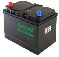
SALIENT FEATURES
Perfect combination of energy storage performance and reliability
Grid plate construction of lead calcium tin alloy giving a 5-8 year design life @ 20°C
Operation at a low internal pressure
Low self-discharge rate (< 3% per month @ 20°C)
Flame-arresting, low-pressure safety release venting system for individual cells, recognized as per U.L.924
Multi-cell design for ease of installation and maintenance
A – The terminal voltage for “AM-6” models is 6V, while that for “AM-12” models is 12V.
B – Ah rating is measured @ 25°C. Wnd voltage per cell (EVPC) for C1=1.55V, C3=1.70V, C5=1.70V, C10=1.75V, and C20=1.75V. The actual battery performance may be ±5% of the figures shown above.
C – SCC means Short Circuit Current and its unit is Amperes.
D – IR means Internal Resistance and its unit is milli-ohms.
E – TT means Terminal Type. 1 means Faston Tab No. 187. 2 means Wire Leads & Plug. 3 means Faston Tab No. 250. 4 means Flag or Insert.
F – Actual dimensions may vary by ±1%.
BATTERY LIFE
Battery life depends on many factors: the actual use of the product (float or cycle service), the sizing (which in turn affects the depth of discharge), method of charging, and operating temperature.
The float service life is also affected by all the above factors. Additionally, it is also affected by the number of cycles that the battery is subjected to and the depth of discharge during each cycle. The more discharges undergone and the deeper the discharge, the shorter the battery life.
Grid-tied solar inverters are inverters used in grid-tied solar PV systems. These inverters are “tied” or “connected” to the grid and used to feed electricity into the grid or to supply electricity to the local loads that are connected to the grid.
Grid-tied solar inverters are broadly classified in two categories:
String inverters: String inverters are grid-tied solar inverters of smaller capacity (1 kW all the way up to 35 kW). They are so called because they allow one or more “strings” of solar PV modules to be connected to them. (A string of solar PV modules is a bunch of solar PV modules connected in series.)
Central inverters: Central inverters are grid-tied solar inverters of high capacity (50 kW all the way up to 1 MW, or even higher in some cases).
We have both string inverters and central inverters.
Note:
Please click on the links to get the detailed specifications of the products.
If you would like to know the price of our grid-tied solar inverters, please send an email to info@cenergymaxpower and we will get back to you ASAP. Please do mention the order size and the place of delivery so that we can give you our best rates and exact delivery times.
String inverters are grid-tied solar inverters of smaller capacity (1 kW all the way up to 35 kW). They are so called because they allow one or more “strings” of solar PV modules to be connected to them. (A string of solar PV modules is a bunch of solar PV modules connected in series.)
EverExceed’s SSB Series grid-tied string inverters use the best patented technology which leads to leading-edge efficiency at a very attractive price. These inverters have proved their worth and established a track record all over the world. Their salient features are:
We have string inverters from 1.6 kW all the way up to 17 kW. Please see the detailed specifications below.
Central inverters are grid-tied solar inverters of high capacity (50 kW all the way up to 1 MW, or even higher in some cases).
EverExceed’s SSC Series grid-tied central inverters are packed with features and give very good value for money. Their salient features are:
High-speed digital DSP + CPLD control technology
Advanced IGBT modules with very high reliability
Pure sine wave output with automatic synchronization with the grid
Low voltage ride-through
Maximum Power Point Tracking efficiency > 99.9%
Multiple protection mechanisms (over-voltage, under-voltage, under-load, short- circuit, islanding, etc.)
Multi-lingual LCD display with easy settings
We have central inverters from 50 kW all the way up to 500 kW. Please see the detailed specifications below.
EverExceed’s PWM solar charge controllers have the following features:
Ideal for solar PV systems
Fully automatic operation
Micro-controller based for high accuracy and precision
Automatic voltage selection (12V or 24V)
Programmable settings for battery Ah setting, boost charge, equalize charge, and float charge
Overcharge and over-discharge protection for the battery
Integrated temperature compensation
Multiple electronic protections and automatic recovery after fault conditions go away
Short circuit (on the input as well as the output side)
Overload (on the input as well as the output side)
Reverse polarity connection
Battery reverse current at night
High voltage
Voltage spikes on the load side
LCD display with system status as symbols, state of charge (SOC) shown as a guage, and all other system parameters in digital values.
EverExceed’sMPPT Solar Charge Controllers, as their name suggests, do maximum power point tracking; they ensure that the solar PV panels always operate at their maximum power point which increases their efficiency compared to PWM solar charge controllers by anywhere from 10% to 30%.
Besides maximum power point tracking, MPPT Solar Charge Controllers have the following features:
Ideal for solar PV systems
Fully automatic operation
Micro-controller based for high accuracy and precision
Automatic voltage selection (12V or 24V)
Programmable settings for battery Ah setting, boost charge, equalize charge, and float charge
Overcharge and over-discharge protection for the battery
Integrated temperature compensation
Multiple electronic protections and automatic recovery after fault conditions go away
Short circuit (on the input as well as the output side)
Overload (on the input as well as the output side)
Reverse polarity connection
Battery reverse current at night
High voltage
Voltage spikes on the load side
LCD display with system status as symbols, state of charge (SOC) shown as a gauge, and all other system parameters in digital values
Secondary Business TypeManufacturer / Exporters / Wholesale Suppliers
Opening Hours
SUN : Closed
MON : 9:30 AM - 6:30 PM
TUE : 9:30 AM - 6:30 PM
WED : 9:30 AM - 6:30 PM
THU : 9:30 AM - 6:30 PM
FRI : 9:30 AM - 6:30 PM
SAT : 9:30 AM - 6:30 PM
Cenergy MaxPower was incorporated in January 2011 to provide Supply Chain Solutions to Offshore Oil and Gas (O & G) and Marine Asset Owners including Shipyards. Cenergy represents leading Original Equipment Manufacturers (OEMs) that have specialized in offering products for the above industries, and provides all the necessary on-site technical assistance including installation and commissioning services.