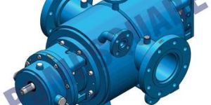
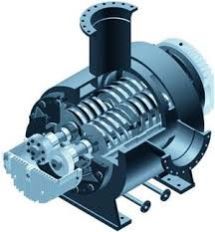
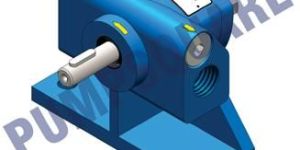
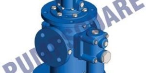
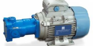
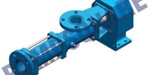
TRIPLE SCREW PUMPS / THREE SCREW PUMPS
Get Latest Price
GENERAL INFORMATION (TH 1X PUMPS)
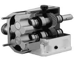
WORKING PRINCIPLE
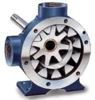
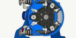
Triple Screw Pumps are positive displacement pumps of very simple design They consist of three rotating parts only the rotors" which turn in their precisely machined housing bores. The rotors are of double start screws, continuously meshing to form delivery chambers, which move constant y from the suction to the pressure / discharge side. Constant volume oi the chambers and the uniformity of the movement allow an even flow The pumps remain therefore near silent in operation and almost free of pulsation, even at high speed The Principle of screw pump and its accurate profiles warrant high suction power. Axial loads on the rotor are compensates by adequate design of the bearing part. All the radial loads are self-compensated.
APPLICATION
Triple Screw Pumps, type TH are used for die transfer of fluids with lubricating properties, as well as for generating pressure in hydraulic units or overcoming pressure in the hydraulic circuits. Main Industrial uses are in:
Power Hydraulics
Power Generation
Lube
industries
Machine Tools
Windmill
Oil & Gas
Compressor Lubrication
Presses
Marine
Filtration
TYPICAL LIQUIDS
All kind of Bunker Oil, Engine oil, Furnace oil, Heating oil, Hydraulic Oils, High Viscosity Lubrication Oil, Mineral oil, Synthetic Oil, 0il Water Emulsions and Fuel 0ils, Diesel Oil, LSHS, LDO.
MATERIAL OF CONSTRUCTION
Pump Housing : Carbon Steel, Cast Iron, Stainless Steel
Liner : Alluminium Alloy / Cast Iron / Copper
Rotors :
Main Screw : Alloy Steel, Hardened Steel and Surface Treated Steel
Idler Screw : Hardened Steel, Surface Treated Steel
Shaft Sealing : Mechanical Seal / Lip Seal with Elastomers in Viton, EPDM & Nitrile / Gland Pack/Graphoil Rings
Mounting Frames : Fabricated Steel
Relief Valve Parts : In Steel & Cast Iron
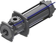
EXECUTION
The pumps here described may be incorporated in various housings and supplied as Foot, Flange or Pedestal Pumps. We also supply cast or welded housings to your specifications. To adapt the pumps to various applications, they can be fitted with the following seal variations:
Radial shaft seals
Gland packings (stuffing box)
Mechanical seals
PRESSURES
Upto 120 bar are admissible.
INSTALLATION
Screw-Pumps work perfectly in any position, provided suction and pressure lines are arranged in a way that prevents emptying of the pump when at a standstill.
DIRECTION OF ROTATION
Clockwise from the Shaft End of the Pump (Standard)
Anticlockwise from the Shaft End of the Pump (On Request / Non Standard)
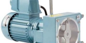
DRIVE
In general the pumps are connected with a flexible coupling to a foot or flange mounted motor. Radial loads onto the shaft end are not permissible, unless when absorbed by an additional external bearing, e.g. in case of pump drive by belts or gears.
SPEED OF ROTATION
Shaft Speed Ranging from 500-3600 RPM
Do not exceed 1500 RPM when pumping residual fuels, crude oil due to the presence of abrasives and contaminants.
VISCOSITY
Normal range 21,5 to 385 cSt. Depending on type, pressure, speed and suction conditions, fluids with viscosities ranging from 6 to 3800 cSt may be pumped. Regarding viscosities outside the normal range.
Please consult us!
TEMPERATURE RANGE
When fitted with standard radial shaft seals, up to 90 Deg C. Depending on operating conditions, temperatures as high as 180 deg C are permissible.
Please ask us!
Cooling Jacket & Heating Jacket for the pump body & covers can be provided for easing the cold start of the pump and for continuously pumping liquids at high temperature.
SUCTION LIFT OR INLET PRESSURE
For speed between 1000 and 1700 r.p.m and viscosities below 385 cSt you may reckon with an absolute manometric suction lift of maximum 0,5 bar. For other speeds or viscosities. Please contact us!
The inlet pressure should not exceed +0,5 bar, when radial shaft seals are used. For higher inlet pressures we offer gland packings or mechanical seals. If the suction lift condition exceeds the pump capability, cavitation will occur resulting in noise and possible pump damage.
SUCTION AND PRESSURE LINES
The cross section of the suction line should be such that fluid velocity nowhere exceeds 1 m/sec. In the pressure line velocity should not exceed 5 m/sec.
PRESSURE RELIEF VALVE
All housings described here may be obtained with or without pressure relief valve, which we supply at your option as by-pass valve, connected to the suction chamber, or as return valve, conducting the fluid by a separate connection to the tank. When a larger quantity should have to pass through the valve for more than 10 seconds, a return valve has to be fitted, to avoid an undue rise in temperature.
FILTRATION
The pumps must be protected against solid particles in the fluid by suitable suction filters. The mesh width should be 0.1 mm and care has to be taken that even with a contaminated filter the admissible suction lift capability is not exceeded.
...more