Audio Video System
Electric Circuit Components & Parts
Mobile Phone & Accessories
Electric & Electronic Active Devices
Audio Recorders, Mixers & Transmitters
Process Control Systems & Equipment
Voltage Stabilizers & Power Controllers
Generators, Turbines & Power Plants
Batteries & Charge Storage Devices
Electrical & Electronic Testing Devices
Measuring Instruments & Equipment
Transformers and Transformer Parts
Inverters, UPS & Converters
Safety System & Equipments
Solar and Renewable Energy Products
Headphones, Speakers & Accessories
Telecommunication Equipment & System
Laboratory Equipments
Gates, Fences and Fencing Materials
Scientific Instruments and Devices
Others
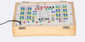
- Semiconductor Devices Characteristics Trainer SB-902
- Electrical Network Circuits and Bridges Lab Trainer Kits
- Measurement of Strain Using Strain Gauge (Digital Display) SE-1016
- EPABX Demonstrator with P & T Interface and Faults Creating Facility SA-904
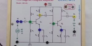
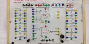
- Linear Integrated Circuits Lab Trainer Kits
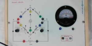
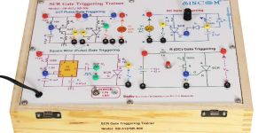
- Characteristics of SCR, DIAC & TRIAC SA-407
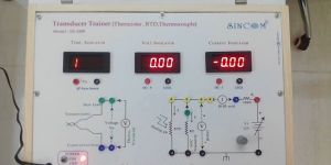
- Transducer Trainer (RTD, Thermister, Thermocouple) SE-1009
- Vocational Training Products Lab Trainer Kits
- Fiber Optics Trainer of Numerical Aperture (NA) & Fiber Cable Losses SE-213
- Color TV Trainer with 30 Faults Creating Facility SA-901
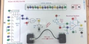
- Optical Communication Trainer with Digital Link SE-202
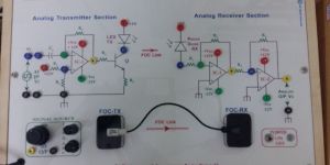
- Optical Communication Trainer with Analog Link SE-201
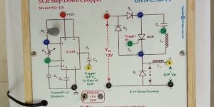
- SCR Step Down Chopper SD-410
- Digital Multimeter Demonstrator SE-812
- Analog Multimeter Demonstrator SE-801
- Line Coding & Decoding Trainer SB-236
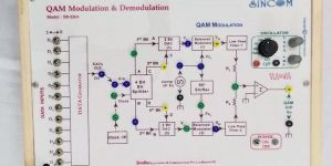
- Advanced Communication Lab Trainer Kits
- Graphic Equalizer Trainer SD 214
- Amplitude (AM) Modulation & Demodulation SA-207
- SA-909 Telephone Demonstrator
- Bread Board Trainer Kits
- Error Detection & Correction Trainer SB-235
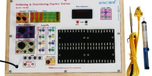
- Soldering & Desoldering Practice Trainer SE-720
- Modem Demonstrator SA-921
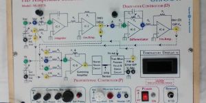
- Instrumentation and Control System Lab Trainer Kits
- Digital Communication Lab Trainer Kits
- Network Bridges Trainer SB-934
- Lab Trainer Kits
- SCR Force Commutation (Turn-OFF Methods)Trainer SB-413
- Measurement of Linear Displacement Using LVDT (Digital) SE-1019