The software must provide the facility to e Configuration and Test Utility for various
zigbee processors etc to know the status of wireless nodes in network. The system
must be supplied with libraries for the ARM Processor for various utilities , for
application programs .This software have the facility to receive the data from number
of xbee nodes and to show the current position of each sensor. It must be provided
with a Serial-Terminal program to interact with XBee modem. Zigbee software is compatible with windows
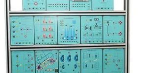
Design: microcontroller arm based ip65 enclosure display: 20*4 lcd display 8 channel analog sensor 6 channel digital sensor 1 modbus channel memory: 8 gb sd card (for available in selected module only). Options: high ratelow ratetrigger modechannel selectionbuzzer alarm. Log interval: 1samplessec to 1sampleweek (user selectable) timing: build in real time clock. Supply: ac operatedbattery operateddc operated. Data storage: in a ms excel sheet, each records are stored with time & date relay interface: can be used to interface a +12v dc component. Data logging: real time with programmable log and storage time. Settings: using a hex keyboard to set the various parameters, to configure the channel and to manually set rate for the sample and hold the channel number
Design: microcontroller arm based ip65 enclosure display: 20*4 lcd display 8 channel analog sensor 6 channel digital sensor 1 modbus channel memory: 8 gb sd card (for available in selected module only). Options: high ratelow ratetrigger modechannel selectionbuzzer alarm. Log interval: 1samplessec to 1sampleweek (user selectable) timing: build in real time clock. Supply: ac operatedbattery operateddc operated. Data storage: in a ms excel sheet, each records are stored with time & date relay interface: can be used to interface a +12v dc component. Data logging: real time with programmable log and storage time. Settings: using a hex keyboard to set the various parameters, to configure the channel and to manually set rate for the sample and hold the channel number
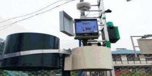
Portable data acquisition system is designed to Record vibration of different type application.
e.g- Machine vibrat i o n , Moving vibration vehic l e s , Building vibration,
Many other application as per requirement
Portable data acquisition system is designed to Record vibration of different type application.
e.g- Machine vibrat i o n , Moving vibration vehic l e s , Building vibration,
Many other application as per requirement
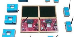
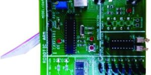
The muldireconal smart robocs system must have the following features Like the hardware setup,
processor setup,and wireless communicaon etc.,Robocs etu.
The muldireconal smart robocs system must have the following features Like the hardware setup,
processor setup,and wireless communicaon etc.,Robocs etu.
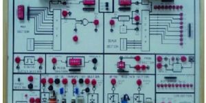
Basic plc (programmable logic control) with digital
input output
allen bradleyseimens wago micrologix plc.
Configurable to both 24v dc & 230vac
built in 24v dc power supply, io led indication on front
line panel
14 inputs, 10 outputs, 2 analog ip & op isolated,
io simulating devices (switches, proximities,
pushbuttons)
experimental panel for analog and digital plc
sequential motor starter interface, star delta starter
interface
dol starter, water level controller, reaction vessel
interface
resistance welding interface, traffic light interface
car parking interface, piston cylinder interface
logic control system
bottle filling system
rack feeder
cascadded control
E2PROM with 4K.memory or more.
RTC DS 1307 with 32 Khz crystal with battery back-up.
Two 12V relays with isolated OPs on 3 pin connectors.
One 12V stepper motors with driver .
All interrupts available on header .
16 X 2 LCD display .
8 IPs available from DIP switches.
8 OPs available on LEDs.
4 multiplexed 7-segment displays.
4-single bit keys, 8 Channel ADC with Potentiometers.
On board DAC Section ,On board Key pad section
Provision of External inputs.
On Board USB and RS232 Communications
The SDR Development Board provides a fully integrated,
Universal Software Radio Peripheral platform with continuous
frequency coverage from 70 MHz –6 GHz. Designed for low-cost experimentation,
it combines a fully integrated direct conversion transceiver providing real-time
bandwidth of 200 kHz to 56 MHz, this is an Xilinx Zynq SIOC based platform compatible
with GNU Radio that allows you to immediately begin developing, to prototype your own communication systems from basic to advance level.
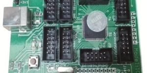
The Arduino Mega 2560 is a microcontroller board based on the ATmega2560It has 54 digital
inputoutput pins (of which 15 can be used as PWM outputs), 16 analog inputs, 4 UARTs
(hardware serial ports), a 16 MHz crystal oscillator, a USB connection, a power jack, an ICSP
header, and a reset button. It contains everything needed to support the microcontroller; simply
connect it to a computer with a USB cable or power it with a AC-to-DC adapter or battery to get started.
ATmega32832 KB (ATmega328) of which 0.5 KB used by bootloader
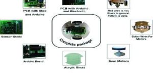
The arduino -bluetooth is a microcontroller board based on The atmega328.it has 14 digital
inputoutput pins (of which 6 can Be used as pwm outputs), 6 analog inputs, a 16 mhz ceramic
resonator, And a reset button. It contains everything needed to support the microcontroller;
Simply connect it to a computer with a usb cable or power it with a ac-to-dc adapter Or battery
to get started. It has bluetooth on board so this board can be Applied to android applications and
wireless applications.
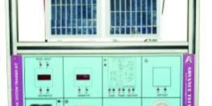
On board test & measuring point in each sect ion.
On board +5v, +12v, -5v power
digital voltmeter.
On board circuit block
on board lcd to check the motor rp m
on board relay
amplifier for various voltage amplifier
On board test & measuring point in each sect ion.
On board +5v, +12v, -5v power
digital voltmeter.
On board circuit block
on board lcd to check the motor rp m
on board relay
amplifier for various voltage amplifier