ANANT ENGINEERING & FABRICATORS Karjat, Ahmednagar, Maharashtra

  • psc pipe

    psc pipe

    Request for Price

    This standard covers the requirements of prestressed concrete pipes (including specials) with nominal internal diameter in the range of 200 mm to 2 500 mm (see Note under Table 1), in which permanent internal stresses are deliberately introduced by tensioned steel to the desired degree to counteract the stresses caused in pipe under service.

    ...more
    Get Best Price
  • penstock pipes

    penstock pipes

    Request for Price

    We are one of the leading Manufacturing Company in Water supply Pipe line accessories like Penstock pipe in a good range.

    ...more
    Get Best Price
  • ms slip expansion joint

    ms slip expansion joint

    Request for Price

    Section 1 : General Sec. 1.1 ScopeThis standard describes fabricated steel mechanical slip-type expansion joints having packing chambers for use on pipe with plain, flanged, grooved, or shouldered ends in nominal pipe sizes from 3 in. through 144 in. (75 mm through 3,600 mm): The joints shall be manufactured from steel and are intended for use in systems conveying water. Mechanical expansion joints are not intended for use in buried conditions. See. 1.2 PurposeThe purpose of this standard is to provide purchasers, manufacturers, and constructors with the minimum requirements for fabricated steel mechanical slip- type expansion joints, including system components, testing, and marking requirements. Sec. 1.3 Application This standard can be referenced in specifications for purchasing and receiving fabricated steel' mechanical slip-type expansion joints and can be used as a guide for inspection and testing. This standard or sections of this standard apply when this document has been referenced and then only to fabricated steel mechanical slip-type expansion joints. Section 2: References This standard references the following documents. In their latest editions, they form a part of this standard to the extent specified within the standard. In any case of conflict, the requirements of this standard shall prevail. ANS(/AWWA C200-Steel Water Pipe-6 In. (150 mm) and Larger. ANSIIAWWA C210-Liquid-Epoxy Coating Systems for the Interior and Exterior of Steel Water Pipelines. ANSIIAWWA C213-Fusion-Bonded Epoxy Coating for the Interior and Exterior of Steel Water Pipelines. ANSIIAWWA C218-Coating the Exterior of Aboveground Steel Water Pipelines and Fittings. ANSII AWWA C220-Stainless-Steel Pipe, 4 In. (100 mrn) and Larger. ANSIIAWWA C224-Two-Layer Nylon-II-Based Polyamide Coating System for the Interior and Exterior of Steel Water Pipe, Connections, Fittings, and Special Sections. ANSIIAWWA C550-Protective Interior Coatings for Valves and Hydrants. ASMEt Bl.I-Unified Inch Screw Threads. ASME B 1. 13M-Metric Screw Threads-M Profile. ASME B 18.2. I-Square and Hex Bolts and Screws Inch Series. ASME BI8.2.2-Square and Hex Nuts. ASME B 18.2.3.6M-Metric Heavy Hex Bolts. ASME B 18.2.4.6M~Metric Heavy Hex Nuts. ASME Boiler and Pressure Vessel Code, Section IX. Section 3: Definitions The following definitions shall apply in this standard: Actual outside diameter: The pipe outside diameter. The diameter of the finished product m~y vary from the actual diameter by the specified tolerances and coating thickness. Body: The main housing assembly includes the packing chamber and bolt ring. One end of the body is attached to the pipeline. Constructor: The party that provides the work and materials for placement or installation. Expansion joint: An assembly that allows compensation for axial move-ment of a water-conveying pipeline. An expansion joint may be single or double ended, with one slip pipe and packing chamber or twO slip pipes and packing chambers, respectively (Figures 1 and 2). Limit ring: A ring or other fixture attached to the slip pipe through which the limit rods pass. Limit rods: Threaded fasteners used to limit the expansion travel of the expansion joints when used in series. The limit rods will activate the adjacent expansion joint when one joint has reached the full limit of its travel (see limit ring). Limit rods are not intended for thrust restraint. Manufacturer: The party that manufactures, fabricates, or produces materials or products. Movement: The amount of pipeline axial expansion or contraction. Nominal Pipe Size: The commercial designation or dimension by which pipe is designated for simplicity. This mayor may not be the same as the actual outside diameter. Packing: Alternating elasrorneric sealing rings and fiber lubricating rings. Packing Bolts: Threaded fasteners used to compress the packing materials of the expansion joint. Packing chamber: A cavity between the body and slip pipe into which the packing is compressed. Packing ring: A cylinder with bolt ring that, with the packing bolts, provides a means of compressing the packing. Also referred to as an end ring, follower, or packing gland. Purchaser: The person, company, or organization that purchases any materials or work to be performed. Rated pressure: Maximum sustained operating pressure under normal operating conditions. Slip pipe: A cylinder that provides a sealing surface for the packing material. One end is attached to the pipeline and the other end slides in and out of the body as the pipeline expands and contracts. Transient pressure: Surge or other pressures that exceed normal operating conditions and are of short duration.

    ...more
    Get Best Price
  • MS PSC Pipe Mould

    MS PSC Pipe Mould

    Request for Price

    This standard covers the requirements of prestressed concrete pipes (including specials) with nominal internal diameter in the range of 200 mm to 2 500 mm (see Note under Table 1), in which permanent internal stresses are deliberately introduced by tensioned steel to the desired degree to counteract the stresses caused in pipe under service. Materials For the purpose of this standard, the following definitions shall apply. 3.1 Prestressed Concrete Cylinder Pipe - A welded sheet steel cylinder with steel socket and spigot rings welded to its ends, lined with concrete suitably compacted and circumferentially prestressed to withstand internal pressure and external design loads and subsequently coated with cement mortar or concrete to protect the steel cylinder and prestressing wires. 3.2 Prestressed Concrete Non - Cylinder Pipe -A suitably compacted concrete I core longitudinally prestressed with pretensioned high tensile steel wire embedded in the concrete, circumferentially pre- stressed and coated with cement mortar or concrete to protect the circumferential prestressing wire, to withstand internal pressure and external design loads. 3.3 Specials - All items in the pipeline other than straight pipes of standard length, such as bends, air valves and scour valve tees, etc, are classified as specials. 3.4 Working Pressure - The maximum sustained internal pressure excluding surge to which each portion of the pipeline may be subjected when installed. 3.5 Site Test Pressure - 1.5 times working pressure pertaining to the section or 1.1 times static pressure, whichever is more (surge pressure is to be controlled within 25 percent of pump head in case of pumping main). 3.6 Factory Test Pressure - a) Site test pressure + 0.1 N/mm2, for working pressure upto 1 N/mm2, and b) Site test pressure + 0.2 Nzmm", for working pressure above 1 N/mm1 3.7 Surge (Water Hammer) Pressure - It is a pressure which is produced by a change of velocity of the moving stream and becomes maximum when there is sudden stoppage which may be caused by the closing of a valve or by shutting down a pump station. Surge pressure is to be controlled within 25 percent of pump head. Materials 4.1 Cement The cement used in the manufacture of prestressed concrete pipes and specials shall be one of the following: 43 grade ordinary Portland cement conforming to IS 8112. S3 grade ordinary Portland cement conforming to IS 12269. Rapid hardening Portland cement conforming to IS 8041. Portland slag cement conforming to IS 455 with slag not more than 50 percent. Sulphate resisting Portland cement conforming to IS 12330.   4.2 Aggregates- The aggregates shall conform to IS 383. The provision of N (Grading) ofIS 383 shall not apply. Manufacturer shall furnish the grading curve for coarse and fine aggregates which he proposes to use. The variation in fineness modulus during manufacture shall not be more than ±5 percent. Silt content in fine aggregates shall be less than 3 percent. The fineness modulus of the aggregates for coating shall be between 2.6 to 3.2. 4.3 Water- Water used for concrete, cement mortar and for curing the pipes shall be free from injurious amounts of oil, acid, strong alkaline scales and vegetable matter and shall be able to make concrete of satisfactory strength requirements 4.4 Admixtures- Admixtures may be used with the approval of the purchaser. However, use of any admixture containing chlorides in any form shall be prohibited. The admixtures shall conform to IS 9103. 4.5 Steel for Reinforcement 4.5.1 Prestressing Steel- Prestressing steel wire shall conform to IS 1785 (Part 1) or IS 1785 (Part 2) or IS 6003 or IS 6006. For longitudinal prestressing, wire having tensile strength, less upto 15 percent of ultimate tensile strength, may be used, if required. This is to avoid excessive wear of rollers for threading, or cracking of wire during button heading for end anchors. 4.5.2 Untensioned Reinforcement - Un tensioned reinforcement may consist of mild steel conforming to IS 432 (Part 1) or IS 432 (Part 2) or high strength deformed bars conforming to IS 1786 or plain hard drawn steel wire conforming to IS 1785 (Part 1) and IS 1785(Part 2) or welded wire fabric conforming to IS 1566. 4.6 Steel for Cylinders and Specials- Steel plates for cylinders and specials shall conform to IS 2062. 4.7 Rubber Sealing Rings 4.7.1 Rubber sealing rings shall comply with IS 5382. The manufacturer of pipe shall examine each sealing ring visually for defects, particularly at the joints. 4.7.2 Every sealing ring shall be clearly marked. The marking shall indicate the chord diameter, internal diameter of the ring and name of the manufacturer of rubber sealing rings. 4.7.3 In case of splices, each splice shall be thoroughly visually checked by twisting the ring through 360°. Splices showing visible separation or cracks shall be rejected. Not more than two splices in each ring shall be permitted. All sealing rings shall be protected from direct rays of the sun and stored in dry place. 4.7.3 In case of splices, each splice shall be thoroughly visually checked by twisting the ring through 360°. Splices showing visible separation or cracks shall be rejected. Not more than two splices in each ring shall be permitted. All sealing rings shall be protected from direct rays of the sun and stored in dry place. 

    ...more
    Get Best Price
  • MS Flange Adaptor

    MS Flange Adaptor

    Request for Price

    The flange adaptor is the most basic type of dismantling joint. On one side, it has a flange connection in accordance with the required flange standard, on the other an insertion socket for the pipe. A variety of standard pipe types can be connected. flange adaptors are available for a variety of pipe types. The anti-torque bolts also make the flange adaptor suitable for a fast “one-man installation”. There are two types of Flange Adapters 1) Weldable Type Flange Adapter 2) Flange Type Flange Adapter The ANANT is equipped with two flanges and one follower end-ring. This design offers optimal gasket control with the separate stud bolts applying pressure to the gasket independently of the tie-rods making the flange connections. This allows a reduction in the number of tie-rods required as their function is restraining only. The AEF - WFA comes equipped with 25 % tie-rods for PN 10 and PN 16 and 50 % tie-rods for PN 25 and PN 40 applications.The AEF - WFA also makes an unrestrained set-up possible. Here no threaded tie-rods are used allowing the dismantling joint to act as a limited expansion joint absorbing noises and vibrations in the pipeline. This variant requires a fixed point in the pipeline. Anchoring is required if the pipe end can be pulled out of the dismantling jointBoth versions of the AEF - WFA are available in the pressure ratings PN 10, PN 16, PN 25 & PN 40 and in nominal sizes of DN 50 to DN 1600, with a standard longitudinal adjustment of ± 25 mm. Connection flanges to any standard are available upon customer request. Larger nominal sizes, higher pressure ratings and non-standard build lengths are also available on request. The AEF - WFA with four flanges and 100 % tie-rods is the ultimate solution for challenging installations. The additional flange results in an increased construction length which makes it possible to slide the threaded tie-rod between end flanges during installation and removal. The AEF - WFA is also suitable in situations where the overall space only just corresponds to the construction length. This allows sideways insertion making the AEF - WFA ideal for cases where the connection flanges are fixed e.g. where pipes protrude out of the wall.The additional flange also makes a time-saving preliminary installation of valves possible. The valve and dismantling joint can be fitted together in the pipeline assembly which are then fitted and clamped together (and removed again) together with the dismantling joint. A further advantage is the continuous threaded tie-rods on one side which makes it possible to remove the valve only.The AEF - WFA can be locked at the required length with adjustability of± 25 mm when installed in pipelines. Connection flanges can also be delivered according to different standards.

    ...more
    Get Best Price
  • MS Dismantling Joints

    MS Dismantling Joints

    Request for Price

    Dismantling Joints play a decisive role in the design and layout of pipelines and valves. They are an essential aid during the installation and removal of pipe sections and valves. Without a dismantling joint offering longitudinal adjustment, it is almost impossible to insert a valve exactly into a pipe section. Thanks to this adjustability of the dismantling joint, the valve can be fitted next to the dismantling joint, and the dismantling joint can be to set to the exact length required prior to being securely connected to flanges. The reverse sequence is used for dismantling, where readjustment of the length of the dismantling joint creates enough space to loosen and remove the valve. In both cases, the dismantling joint guarantees fast installation and removal, thus contributing to increased efficiency and reducing site operations and down time. The procedure is similar where pipe sections have to be fitted together. Certain types of dismantling joints are also suitable for use without restraint in flexible pipelines. Finally, dismantling joints can be used to fill gaps e.g. where a pump installed in a fixed position has to be connected to a pipe protruding from a wall.

    ...more
    Get Best Price
  • Mechanical Joints

    Mechanical Joints

    Request for Price

    Section 1 : General Sec. 1.1 Scope - This standard describes bolted, sleeve-type couplings, reducing or transition couplings, and flanged coupling adapters used to join plain-end steel and ductile-iron pipe. They may be manufactured from carbon steel, stainless steel, ductile iron, or malleable iron, and are intended for use in systems conveying water. This standard describes nominal pipe sizes from V2 in. (]3 mm)' through 114 in. (3,600 m) Sec. 1.2 Purpose - The purpose of this standard is to provide the minimum requirements 19r bolted, sleeve-type couplings for plain-end pipe, including requirements for materials, design, testing and inspection, installation, and shipping Sec. 1.3 Application - This standard can be referenced in specifications for bolted, sleeve-typo couplings for plain-end pipe. The stipulations of this standard apply when this document has been referenced and then only to bolted, sleeve-type couplings for plain-end pipe. Section 2: Definitions 
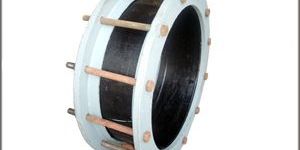
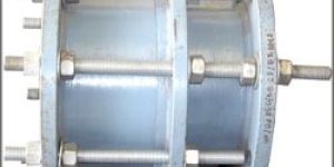
The following definitions shall apply in •this standard (refer to Figures 1 and 2):  Actual outside diameter: The pipe outside diameter (including any coating) Angular deflection: The angle between the longitudinal axes of the pipes being joined by the coupling. 
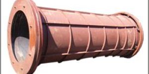
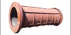
Center sleeve (center ring, middle ring): A cylinder of sufficient length to fully enclose both pipe ends. Constructor: The party that provides the work and materials for placement or instalIation. 
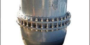
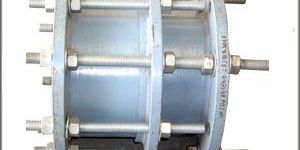
Coupling: An assembly consisting of a center sleeve, gaskets, and end rings connected with bolts and nuts or other type of threaded fasteners. Tightening the fasteners transfers the load through the end rings and compresses the gaskets into the space between the inside of the center sleeve and the outside surface of" the pipe ends. Design pressure: See rated pressure. End ring (follower ring): A ring that provides a means of compressing the coupling gasketts). Flanged coupling adapter: A coupling used to connect plain-end pipe to a flange. It consists of a flange, center sleeve, gasket, and an end ring connected with bolts and nuts or other threaded fasteners. Gasket: An elastomeric ring that provides the pressure seal of the coupling. Manufacturer: The party that manufactures, fabricates, or produces the materials or products. Nominal pipe size: The commercial designation or dimension by which the pipe is identified. The designation may not be the same as the actual inside diameter. Purchaser: The person, company, or organization that purchases any materials or work to be performed. Rated pressure: The maximum internal hydrostatic pressure to which the coupling is to be subjected under normal operating conditions. In addition, transient and test pressures should be considered in design by the purchaser. Reducing coupling: A coupling that uses end rings of different sizes and a center sleeve with ends of proper inside diameter to join pipes of different outside diameters. The center sleeve may be a single piece or several pieces sized to accommodate the different pipe diameters. Transient pressure: Surge or other pressures that exceed normal operating conditions and are of short duration. Transition coupling: A coupling used to join pipe of the same nominal size. but of differing outside diameters. Differences in pipe outside diameters are accomrno- dated by specially sized gaskets and, when necessary, specially sized end rings. Insulating coupling: A coupling used to break electrical continuity between two pipes. This is normally done by means of special insulating gaskets.

    ...more
    Get Best Price
  • Flanges

    Flanges

    Request for Price

    We are among the distingushed names in the industru for manufacturing and supplying large Diameter flanges. The offered products are made in tune with the international standards for catering to a huge clientele based in india and across the globe. These are used for fastening large piping systems and are dimensionally accurate. Manufactured form high quality stainless steel, these flanges are resistant to high pressure. We hold the proficiency in offering premium quality large diameter flanges. This product is precisely designed and developed under the guidance of skilled professionals using latest machines and premium quality raw material. In addition to this, our offered range is precisely tested on well-defined parameters of quality in order to offer perfect range at clients end. This is highly appreciated in the market. Thik - 10mm, Range - 150mm, 100 NB to 3200 NB We manufacture as per standard as IS-1538 table 4 & 6 IS - 6392 table 13 ASME/ANSI B16.5, ASME/ANSI B16.36, ASME/ANSI B16.47 Series A ( MSS SP-44), Series B ( API 605), BS4504, EN-1092, AWWA C207, UNI 2276-67, DIN, JIS, BS 10 : 1962, IS:6392-1971, API 6A etc.

    ...more
    Get Best Price
  • Flange Adaptors

    Flange Adaptors

    Request for Price

    The flange adaptor is the most basic type of dismantling joint. On one side, it has a flange connection in accordance with the required flange standard, on the other an insertion socket for the pipe. A variety of standard pipe types can be connected. flange adaptors are available for a variety of pipe types. The anti-torque bolts also make the flange adaptor suitable for a fast “one-man installation”.

    ...more
    Get Best Price
  • Dismantling Joint

    Dismantling Joint

    Request for Price

    Dismantling Joints play a decisive role in the design and layout of pipelines and valves. They are an essential aid during the installation and removal of pipe sections and valves. Without a dismantling joint offering longitudinal adjustment, it is almost impossible to insert a valve exactly into a pipe section. Thanks to this adjustability of the dismantling joint, the valve can be fitted next to the dismantling joint, and the dismantling joint can be to set to the exact length required prior to being securely connected to flanges.

    ...more
    Get Best Price
  • Teflon Thrust Bearing Set

    Teflon Thrust Bearing Set

    Request for Price

    Get Best Price
  • carbon thrust bearing

    carbon thrust bearing

    Request for Price

    Get Best Price

Be first to Rate

Rate This

Select the service for which you are writing review for this business

How would you rate the business?

What would you like other to know about this business, based on your experience?

Minimum 20 characters!

About the Company

  • Primary Business Retailer
  • Secondary Business Type Manufacturer / Exporters / Wholesale Suppliers

Opening Hours

  • SUN : Closed
  • MON : 9:30 AM - 6:30 PM
  • TUE : 9:30 AM - 6:30 PM
  • WED : 9:30 AM - 6:30 PM
  • THU : 9:30 AM - 6:30 PM
  • FRI : 9:30 AM - 6:30 PM
  • SAT : 9:30 AM - 6:30 PM
M/s. Anant Engineers & Fabricators is one of the leading Manufacturing Company in Water supply Pipe line accessories in India. Company Est. 1978 as a Propritory unit and comes under SME.
This company is a part Business Group company ANANT. Another four sister company also in the same business circles.
Last year ANANT Group Sales is € 17 Million in all is products.
This Group company is a family business and Founder of this group Mr. Nandkishor Natu having 35 years’ Experience by doing the business with Water supply Schemas in India.
Read More »

Contact Information

ANANT ENGINEERING & FABRICATORS

  • ANANT ENGINEERING & FABRICATORS
  • MIDC., Plot No. D/37, - 414 111 , ., Karjat, Ahmednagar, Maharashtra
top