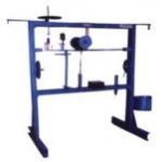
VIB-LAB. , is useful to study various experiments and to verify the principles and relations pertaining to study of vibrations. In this apparatus frame and stand made out of thick M.S.channels are provided for conducting various experiments related to vibration. While designing special care is taken for quick and easy assembly and dismantling of experimental set-ups. Digital RPM Indicator is provided for measuring speed of the exciter unit
VIB-LAB. , is useful to study various experiments and to verify the principles and relations pertaining to study of vibrations. In this apparatus frame and stand made out of thick M.S.channels are provided for conducting various experiments related to vibration. While designing special care is taken for quick and easy assembly and dismantling of experimental set-ups. Digital RPM Indicator is provided for measuring speed of the exciter unit
The set-up is designed to study the working of different governors normally used to control the speed. It consists of a main spindle, mounted vertically on the base plate. This spindle is driven by a variable speed Motor which is also mounted vertically on the same base plate. Anyone governor assembly out of four can be mounted on spindle. Speed control unit controls the spindle speed. A graduated scale is fitted to the sleeve to measure the displacement.
The set-up is designed to study the working of different governors normally used to control the speed. It consists of a main spindle, mounted vertically on the base plate. This spindle is driven by a variable speed Motor which is also mounted vertically on the same base plate. Anyone governor assembly out of four can be mounted on spindle. Speed control unit controls the spindle speed. A graduated scale is fitted to the sleeve to measure the displacement.
The present apparatus is designed to determine thermal conductivities of different liquids. The apparatus consists of a heater. The heater heats a thin layer of liquid. A cooling plate removes heat through liquid layer, ensuring unidirectional heat flow. Temperature is measur d across the liquid layer and complete assembly is properly insulated. A proper arrangement for changing the liquids is provided. The whole assembly is kept in chamber.
The present apparatus is designed to determine thermal conductivities of different liquids. The apparatus consists of a heater. The heater heats a thin layer of liquid. A cooling plate removes heat through liquid layer, ensuring unidirectional heat flow. Temperature is measur d across the liquid layer and complete assembly is properly insulated. A proper arrangement for changing the liquids is provided. The whole assembly is kept in chamber.
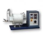
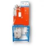
Insulating Powder Apparatus is designed to determine the thermal conductivity of insulating powder. The Apparatus consists of two thin walled concentric copper spheres. Inner sphere houses Nichrome Wire heating coil. Insulating powder is filled between the spheres. Heat flows radially outwards. Temperature sensors at proper positions are fitted to measure surface temperatures of spheres. Heat input to the heater is given through a Variac and measured by Digital Voltmeter & Digital Ammeter. By varying the heat input rates, wide range of experiments can be performed.
...more
Thermal Conductivity of Insulating Powder Apparatus
Insulating Powder Apparatus is designed to determine the thermal conductivity of insulating powder. The Apparatus consists of two thin walled concentric copper spheres. Inner sphere houses Nichrome Wire heating coil. Insulating powder is filled between the spheres. Heat flows radially outwards. Temperature sensors at proper positions are fitted to measure surface temperatures of spheres. Heat input to the heater is given through a Variac and measured by Digital Voltmeter & Digital Ammeter. By varying the heat input rates, wide range of experiments can be performed.
The experimental set up consists of metal bar, one end of which is heated by an electric heater while the other end of the bar projects inside the cooling water jacket. A cylindrical shell filled with the asbestos insulating powder surrounds the middle portion of the bar. The temperature of the bar is measured at different sections. Heat Input to the heater is given through Variac and measured by Digital Voltmeter & Digital Ammeter. By varying the heat input rates, wide range of experiments can be performed. Water under constant head condition is circulated through the jacket and its flow rate and temperature rise is noted.
The experimental set up consists of metal bar, one end of which is heated by an electric heater while the other end of the bar projects inside the cooling water jacket. A cylindrical shell filled with the asbestos insulating powder surrounds the middle portion of the bar. The temperature of the bar is measured at different sections. Heat Input to the heater is given through Variac and measured by Digital Voltmeter & Digital Ammeter. By varying the heat input rates, wide range of experiments can be performed. Water under constant head condition is circulated through the jacket and its flow rate and temperature rise is noted.
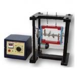
This equipment is designed for carrying out the experiment for balancing a rotation mass system. The apparatus consists of a steel shaft fixed in a rectangular frame. A set of four clamping arrangement is provided. For static balancing, each block is individually clamped on shaft and its relative weight is found out using cord and container system in terms of number of steel balls. For dynamic balancing, a moment polygon is drawn using relative weights and angular and axial position of blocks is determined. The block are clamped on shaft is rotated by a motor to check dynamic balance of the system. The system is provided with angular and longitudinal scales and is suspended with chains for dynamic balancing.
This equipment is designed for carrying out the experiment for balancing a rotation mass system. The apparatus consists of a steel shaft fixed in a rectangular frame. A set of four clamping arrangement is provided. For static balancing, each block is individually clamped on shaft and its relative weight is found out using cord and container system in terms of number of steel balls. For dynamic balancing, a moment polygon is drawn using relative weights and angular and axial position of blocks is determined. The block are clamped on shaft is rotated by a motor to check dynamic balance of the system. The system is provided with angular and longitudinal scales and is suspended with chains for dynamic balancing.
It consists of two concentric chambers, the inner chamber and the outer chamber, which communicates with each other through an opening at the top. As the steam discharges through the metal basket, which has a large number of holes, the water particles due to their heavier momentum get separated from the steam and collect in the chamber. The comparatively dry steam in the inner chamber moves up and then down aging through the annular space between the two chambers and enters the Throttling Calorimeter.
It consists of two concentric chambers, the inner chamber and the outer chamber, which communicates with each other through an opening at the top. As the steam discharges through the metal basket, which has a large number of holes, the water particles due to their heavier momentum get separated from the steam and collect in the chamber. The comparatively dry steam in the inner chamber moves up and then down aging through the annular space between the two chambers and enters the Throttling Calorimeter.
The present set-up consists of a runner. The buckets are mounted on the runner. The water is fed to the turbine, through SS nozzle with a SS spear, by means of Cent al Pump, tangentially to the runner. Row of water into turbine is regulated by adjusting the spear position by the help of a given hand wheel The runner is directly mounted on one end of a central SS shaft and other end is connected to a brake arrangement. The circular window of the turbine casing is provided with a transparent acrylic sheet for observation of flow on to the buckets. This runner assembly is supported by rigid MS structure. Load is applied to the turbine with the help of this brake dynamometer so that the efficiency of the turbine can be calculated. Pressure gauge is fitted at the inlet of the turbine to measure the total supply head to the turbine.
The present set-up consists of a runner. The buckets are mounted on the runner. The water is fed to the turbine, through SS nozzle with a SS spear, by means of Cent al Pump, tangentially to the runner. Row of water into turbine is regulated by adjusting the spear position by the help of a given hand wheel The runner is directly mounted on one end of a central SS shaft and other end is connected to a brake arrangement. The circular window of the turbine casing is provided with a transparent acrylic sheet for observation of flow on to the buckets. This runner assembly is supported by rigid MS structure. Load is applied to the turbine with the help of this brake dynamometer so that the efficiency of the turbine can be calculated. Pressure gauge is fitted at the inlet of the turbine to measure the total supply head to the turbine.
The set up consists of heavy disc mounted on a horizontal shaft, rotated by a variable speed motor. The rotor shaft is coupled to a motor mounted on a mullion frame having bearings in a yoke frame, which is free to rotate about vertical axis. A weight pan on other side of disc balances the weight of motor. Rotor disc can be move about three axis. Torque can be applied by calculating the weight and distance of weight from the center of rotor. The gyroscopic couple can be determined.
The set up consists of heavy disc mounted on a horizontal shaft, rotated by a variable speed motor. The rotor shaft is coupled to a motor mounted on a mullion frame having bearings in a yoke frame, which is free to rotate about vertical axis. A weight pan on other side of disc balances the weight of motor. Rotor disc can be move about three axis. Torque can be applied by calculating the weight and distance of weight from the center of rotor. The gyroscopic couple can be determined.
We offer premium quality array of upright metallurgical microscope. Designed in compliance with international quality standards these are extensively used for microscopical observation of surfaces of non-transparent object. The body of microscope comprises the co-axial focusing system provided With pre- focusing lever, large knob and tension adjustment ring. There is Quadruple nose piece on ball bearing and the mechanical stage is 274mmX274mm with co-axial controls on ball bearing guide ways.
We offer premium quality array of upright metallurgical microscope. Designed in compliance with international quality standards these are extensively used for microscopical observation of surfaces of non-transparent object. The body of microscope comprises the co-axial focusing system provided With pre- focusing lever, large knob and tension adjustment ring. There is Quadruple nose piece on ball bearing and the mechanical stage is 274mmX274mm with co-axial controls on ball bearing guide ways.
The present set-up consists of a scroll casing housing a runner. Water enters the turbine through the stationary guide vanes and passes through the runner axially. The runner has a hub and airfoil vanes, which are mounted on it. The water is fed to the turbine by means of Centrifugal Pump. The runner is directly mounted on one end of a central SS shaft and other end is connected to a brake arrangement. A transparent hollow cylinder made of acrylic is fitted in between the draft tube and the casing for observation of flow. Load is applied to the turbine with the help of rope brake arrangement so that the efficiency of the turbine can be calculated. The set-up is supplied with control panel. A draft tube is fitted on the outlet of the turbine. The set-up is complete with guide mechanism. Pressure and Vacuum gauges are fitted at the inlet and outlet of the turbine to measure the total supply head on the turbine.
The present set-up consists of a scroll casing housing a runner. Water enters the turbine through the stationary guide vanes and passes through the runner axially. The runner has a hub and airfoil vanes, which are mounted on it. The water is fed to the turbine by means of Centrifugal Pump. The runner is directly mounted on one end of a central SS shaft and other end is connected to a brake arrangement. A transparent hollow cylinder made of acrylic is fitted in between the draft tube and the casing for observation of flow. Load is applied to the turbine with the help of rope brake arrangement so that the efficiency of the turbine can be calculated. The set-up is supplied with control panel. A draft tube is fitted on the outlet of the turbine. The set-up is complete with guide mechanism. Pressure and Vacuum gauges are fitted at the inlet and outlet of the turbine to measure the total supply head on the turbine.
Our extensive range of Jominy End Quenching Apparatus is high on demand in market for its high efficiency and durability. This apparatus is used for determining the harden ability of steel by a Quench
Test experiment which enables the lab technocrat to know about the harden ability characteristics of different alloying elements. Designed as per Indian and International Standards the standard specimen from furnace is placed in the apparatus for quick end quench under standard water jet and nozzle diameter
Apparatus consists of a close circuit through which water is circulated continuously by means of a centrifugal pump of 25 mm x 25 mm with
0.5 H.P. motor to make the supply from sump tank. A sump tank 125 cm long, 80 cm wide and 40 cm high fabricated on MS. angle frame with 3 mm thick M.S. sheet is provided. Inside of the tank is lined with FRP. A drain valve of 15 mm size is provided in the bottom of the tank.
A supply tank 50 cm x 50 cm and 100 cm high fabricated with SS. sheet with over flow arrangement, gauge glass tube and 15 mm size drain valve is provided. Inside of the tank is lined with FRP. The tank has the provision for fixing the supply pipe of 50 mm dia of which other end is connected to the ram. The tank is supported on a stand fabricated from MS. angle.
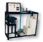
The setup consists of a brass tube fitted in a rectangular duct in a vertical fashion. The duct is open at the top and bottom, and forms an enclosure and serves the purpose of undisturbed surrounding. One side of the duct is fitted with a transparent good quality Acrylic window for visualization. An electric heating element is kept in the vertical tube that in turns heats the tube surface. The heat is lost from the tube to the surrounding air by natural convection. The temperature of the vertical tube is measure by Temperature Sensors and displayed by a Digital Temperature Indicator with multi-channel switch. The heat input to the heater is measured by a Digital Ammeter and a Digital Voltmeter and is varied by a Variac. The tube surface is polished to minimize the radiation losses.
The setup consists of a brass tube fitted in a rectangular duct in a vertical fashion. The duct is open at the top and bottom, and forms an enclosure and serves the purpose of undisturbed surrounding. One side of the duct is fitted with a transparent good quality Acrylic window for visualization. An electric heating element is kept in the vertical tube that in turns heats the tube surface. The heat is lost from the tube to the surrounding air by natural convection. The temperature of the vertical tube is measure by Temperature Sensors and displayed by a Digital Temperature Indicator with multi-channel switch. The heat input to the heater is measured by a Digital Ammeter and a Digital Voltmeter and is varied by a Variac. The tube surface is polished to minimize the radiation losses.
Set up consists of a gear pump having a pair of meshed gears coupled with electrical motor, supply tank, measuring tank & pipe fittings for closed loop oil circulation. Pressure and Vacuum gauges are connected on delivery and suction side of pump for the purpose of measurement. The flow rate of water is measured using measuring tank and stop watch provided.
Set up consists of a gear pump having a pair of meshed gears coupled with electrical motor, supply tank, measuring tank & pipe fittings for closed loop oil circulation. Pressure and Vacuum gauges are connected on delivery and suction side of pump for the purpose of measurement. The flow rate of water is measured using measuring tank and stop watch provided.
The present set-up consists of a runner. The water is fed to the turbine by Means of Centrifugal Pump, radially to the runner. The runner is directly mounted on one end of a central SS shaft and other end is connected to a brake arrangement. The circular window of the tu ine casing is provided with a transparent acrylic sheet for observation of flow on to the runner. Load is applied to the turbine with the help of brake arrangement so that the efficiency of the turbine can be calculated. A draft tube is fitted on the outlet of the turbine. The set-up is complete with guide mechanism. Pressure and Vacuum gauges are fitted at the inlet and outlet of the turbine to measure the total supply head on the turbine.
The present set-up consists of a runner. The water is fed to the turbine by Means of Centrifugal Pump, radially to the runner. The runner is directly mounted on one end of a central SS shaft and other end is connected to a brake arrangement. The circular window of the tu ine casing is provided with a transparent acrylic sheet for observation of flow on to the runner. Load is applied to the turbine with the help of brake arrangement so that the efficiency of the turbine can be calculated. A draft tube is fitted on the outlet of the turbine. The set-up is complete with guide mechanism. Pressure and Vacuum gauges are fitted at the inlet and outlet of the turbine to measure the total supply head on the turbine.
The present Setup is designed to measure the emissivity of test plate. The test plate comprises of a mica heater sandwiched between two circular plates. Black plate is identical with test plate, but its surface is blackened. As all the physical properties, dimension and temperature are equal; heat losses from both plates will be same except radiation loss. Hence the input difference will be due to difference in emissivity. Both plates are supported on individual brackets in a wooden enclosure with one side glass to ensure steady atmospheric conditions. Temperature Sensors are provided to measure the temperature of each plate and surrounding. Supply is given to heaters through separate Variac so that temperatures of both can be kept equal and is measured with Digital Voltmeter and Digital Ammeter.
The present Setup is designed to measure the emissivity of test plate. The test plate comprises of a mica heater sandwiched between two circular plates. Black plate is identical with test plate, but its surface is blackened. As all the physical properties, dimension and temperature are equal; heat losses from both plates will be same except radiation loss. Hence the input difference will be due to difference in emissivity. Both plates are supported on individual brackets in a wooden enclosure with one side glass to ensure steady atmospheric conditions. Temperature Sensors are provided to measure the temperature of each plate and surrounding. Supply is given to heaters through separate Variac so that temperatures of both can be kept equal and is measured with Digital Voltmeter and Digital Ammeter.
Two Stage Air Compressor Test Rig consists of a double stage reciprocating type air compressor driven by 2 HP Motor through a belt. The outlet of the air compressor is connected to reservoir (Tank) and suction is connected to another air tank with a calibrated orifice plate and a water manometer. Bellow is fitted on one side of the air tank to regulate the flow. Temperature of inlet air, after single compression, inlet and outlet of second compression and pressure in reservoir and at intermediate stage can be measured by thermometers and gauges.
Two Stage Air Compressor Test Rig consists of a double stage reciprocating type air compressor driven by 2 HP Motor through a belt. The outlet of the air compressor is connected to reservoir (Tank) and suction is connected to another air tank with a calibrated orifice plate and a water manometer. Bellow is fitted on one side of the air tank to regulate the flow. Temperature of inlet air, after single compression, inlet and outlet of second compression and pressure in reservoir and at intermediate stage can be measured by thermometers and gauges.
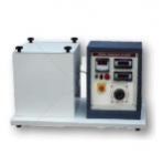
We offer premium quality range of double desk polishing machine extensively used for polishing metallographic samples. Procured from our reliable vendors these are provided with double disc, driven by high torque DC motor. The paper holding band and water faucet enhances drywet grinding and assist in final lapping. Used for microscopic observation to study metal structures, these machines are finely polished to ensure smooth, scratch free and mirror like appearance that enable accurate metallographic interpretation.
We offer premium quality range of double desk polishing machine extensively used for polishing metallographic samples. Procured from our reliable vendors these are provided with double disc, driven by high torque DC motor. The paper holding band and water faucet enhances drywet grinding and assist in final lapping. Used for microscopic observation to study metal structures, these machines are finely polished to ensure smooth, scratch free and mirror like appearance that enable accurate metallographic interpretation.
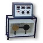
Light weight with ceramic fibre wooled insulation (instead of brick insulation). The outer casing is made of double walled thick P.C.R.C. sheet, reattached with thick perforated sheet on the bottom portion, powder coated. Heating elements are made of KANTHAL "A-1" wire and backed by high temperature cerwool insulation, which avoids loss of energy. Digital Temperature controller unit consists of Energy Regulator, fitted in front of furnace with two pilot lamps. To work on 220230 volts. Maximum Temp. is 1200ºC and working Temp. 1100ºC.
Light weight with ceramic fibre wooled insulation (instead of brick insulation). The outer casing is made of double walled thick P.C.R.C. sheet, reattached with thick perforated sheet on the bottom portion, powder coated. Heating elements are made of KANTHAL "A-1" wire and backed by high temperature cerwool insulation, which avoids loss of energy. Digital Temperature controller unit consists of Energy Regulator, fitted in front of furnace with two pilot lamps. To work on 220230 volts. Maximum Temp. is 1200ºC and working Temp. 1100ºC.
Set up consists of a centrifugal pump coupled with electrical motor, supply tank, measuring tank & pipe fittings for closed loop water circulation. Pressure and Vacuum gauges are connected on delivery and suction side of pump for the purpose of measurement. The flow rate of water is measured using measuring tank and stop watch provided.
Set up consists of a centrifugal pump coupled with electrical motor, supply tank, measuring tank & pipe fittings for closed loop water circulation. Pressure and Vacuum gauges are connected on delivery and suction side of pump for the purpose of measurement. The flow rate of water is measured using measuring tank and stop watch provided.
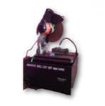
General purpose abrasive saw suitable for site use. Supplied with abrasive disc suitable for metal-cutting but will cut concrete with correct blade fitted. Trigger operated, 2200W motor and hardened gears give smooth transmission of power. Fitted with mitre vice.
General purpose abrasive saw suitable for site use. Supplied with abrasive disc suitable for metal-cutting but will cut concrete with correct blade fitted. Trigger operated, 2200W motor and hardened gears give smooth transmission of power. Fitted with mitre vice.