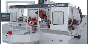
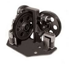
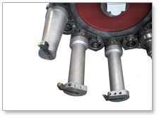
The"Modulo Equipe" unit combines the advantages offered by rotating-part machining with those of stationary-part machining.
This unit ensures high productivity together with a remarkable flexibility, which allows to perform machining operations on a variety of parts, with extremely easy tool-change.
This high degree of flexibility is made possible by a turret with six tool-holder stations, that can take tips, taps, multiple-spindle heads and above all rotary-tool turning heads.
These rotary-tool turning heads, which perform a radial movement, allow to perform all types of turning (cylindrical, taper or spherical turning), thread cutting (cylindrical and tapered), facing, etc., by means of standard tools commonly found on the market.
Turning heads2: 220 mm travel 50 mm, 2: 180 mm travel 30mm
Individual spindle ends6 cylindrical Ø 48
Adjustable multiple-spindle heads1 with 4 spindles
Spindle motor power18 Kw (24 HP)
Max. spindle speed1500
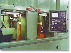
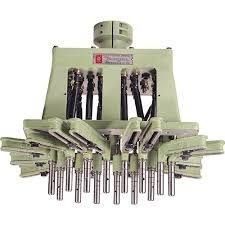
This is a CNC special purpose machine which incorporates two Modulo Equipe "1" units one opposite the other and 2 self-centering chucks, suitable for clamping special shafts.These units allow to work each individual part on both sides simultaneously and to perform turning operations by means of CNC rotary-tool turning heads, as well as all types of drilling/tapping jobs. The bed and self-centering chucks are made of electro-welded metal plate, subjected to a stress-relieving treatment.Both the units and the chucks slide along the same guides, for increased positioning accuracy. All motors are Brushless type and the chucks - which can hold small parts as well as large ones- adjust automatically. This machine can optionally be fitted with an automatic loader/unloader manipulator.
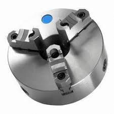
SELF-CENTERING CHUCKS
Clamping
Hydraulic/mechanical, self-centering, with motor and screw
Jaws
"V"-shaped, universal, with small and large parts
SELF-CENTERING CHUCKS
CNC
GE Fanuc
Hydraulic components
Rexroth
This is a CNC special purpose machine which incorporates two Modulo Equipe "1" units one opposite the other and 2 self-centering chucks, suitable for clamping special shafts.These units allow to work each individual part on both sides simultaneously and to perform turning operations by means of CNC rotary-tool turning heads, as well as all types of drilling/tapping jobs. The bed and self-centering chucks are made of electro-welded metal plate, subjected to a stress-relieving treatment.Both the units and the chucks slide along the same guides, for increased positioning accuracy. All motors are Brushless type and the chucks - which can hold small parts as well as large ones- adjust automatically. This machine can optionally be fitted with an automatic loader/unloader manipulator.
SELF-CENTERING CHUCKS
Clamping
Hydraulic/mechanical, self-centering, with motor and screw
Jaws
"V"-shaped, universal, with small and large parts
SELF-CENTERING CHUCKS
CNC
GE Fanuc
Hydraulic components
Rexroth
TheFacing head is integrated into the headstock above the Main Spindle.The Position of the Facing Head is important in context of covering the diameter range. The Main Spindle slides inside the headstock, allowing the Facing head to rotate for its full range from Zero to Maximum diameter of its Model designed. The “U” axis travel varies for each Model. Please see the Technical sheet for details. The Facing diameter of the U axis slide is controlled by CNC command. The slide has more than one tool mounting positions from Model DS 450 for diameter flexibility this helps to cover the entire Range of the Diameters from minimum to Maximum diameters and Tools are loaded automatically from the tool magazine to one of thefirst or secondor thirdmounting positions. The Tool mounted on Facing Head can be used for single-point facing, boring, turning and threading operations. Standard tooling is employed at any programmed diameter to rough and finish complex internal and external profiles. Extra-large tools can be loaded automatically from a tool rack or spare pallet station, such as very long and heavy angle head attachments. The turning speed is fully programmable with constant surface speed control as on a conventional CNC lathe.
TheFacing head is integrated into the headstock above the Main Spindle.The Position of the Facing Head is important in context of covering the diameter range. The Main Spindle slides inside the headstock, allowing the Facing head to rotate for its full range from Zero to Maximum diameter of its Model designed. The “U” axis travel varies for each Model. Please see the Technical sheet for details. The Facing diameter of the U axis slide is controlled by CNC command. The slide has more than one tool mounting positions from Model DS 450 for diameter flexibility this helps to cover the entire Range of the Diameters from minimum to Maximum diameters and Tools are loaded automatically from the tool magazine to one of thefirst or secondor thirdmounting positions. The Tool mounted on Facing Head can be used for single-point facing, boring, turning and threading operations. Standard tooling is employed at any programmed diameter to rough and finish complex internal and external profiles. Extra-large tools can be loaded automatically from a tool rack or spare pallet station, such as very long and heavy angle head attachments. The turning speed is fully programmable with constant surface speed control as on a conventional CNC lathe.
Adjustable multiple-spindle heads5 with 8 spindles
Spindle motor power22 Kw each (30 HP)
Max. spindle speed1250
SlidesCross-roller guide shoes
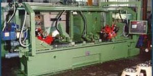
This special CNC Machine is used to machine valve bodies and is designed to reduce machining time to a minimum, by working each part on three faces simultaneously. This machine incorporates 3 modules with 6-position turrets, using 2 modulo equipe "2" horizontal units, with 22kw spindle motor, and 1 modulo equipe "1" vertical unit, with 18kw spindle motor.Each unit is fitted with turning heads and adjustable spindle, multiple drilling/tapping heads. The machine bed and column are made of electro-welded metal plate, subjected to post-weld stress-relieving process, and are designed so as to provide ample space for collecting coolant and chips.This machine is equipped with Brushless motors and cross-roller guide shoes.It comes complete with 2-station pallet changer, fitted with self-centering gripping jaws.
MODULO EQUIPE "1" VERTICAL
Turret positions
6
Turning heads
1: 180 mm travel 30 mm, 2: Ø 220 travel 50 mm
Fixed multiple-spindle heads
2 with 4 spindles
Individual spindle attachments
1 cylindrical Ø 48
Spindle motor power
18 Kw (24 HP)
Max. spindle speed
1500
Slides
Cross-roller guide shoes
SELF-CENTERING GRIPPING JAWS
Clamping
Mechanical, with self-centering draw-in bolt
Jaws
Replaceable, with reference slots and central draw-in bolt
PALLET CHANGER
Number of stations
2 stations 180° apart
Handling
Hydraulic feed
COMPONENTS
CNC
GE Fanuc
Motors, drives
GE Fanuc
Hydraulic components
Rexroth
Description of Technical Features
The Trevisan Horizontal Machining Centres combine the advantages offered by a stationary-part machining with those of rotating-part machining. In-case of a rotating part in Vertical turning Lathe the Cutting speed is restricted due to the diameter of the chuck peripheral Speed. This result in not able utilizes the maximum cutting speed allowed.
To achieve an optimized solution Trevisan Machines aredesigned with a Facing Head. The diameter of the Facing Head varies depending on the model. They are smaller for small diameter machining& bigger for bigger diameter Machining. So that higher RPM can be achieved to optimize the cutting. Also to achieve the above a specially designed Gear Box to generate an incredible Torque. Finally to deliver the power generated to the Tool, a genius Patent tool holder.
TheFacing head is integrated into the headstock above the Main Spindle.The Position of the Facing Head is important in context of covering the diameter range. The Main Spindle slides inside the headstock, allowing the Facing head to rotate for its full range from Zero to Maximum diameter of its Model designed. The “U” axis travel varies for each Model. Please see the Technical sheet for details. The Facing diameter of the U axis slide is controlled by CNC command. The slide has more than one tool mounting positions from Model DS 450 for diameter flexibility this helps to cover the entire Range of the Diameters from minimum to Maximum diameters and Tools are loaded automatically from the tool magazine to one of thefirst or secondor thirdmounting positions. The Tool mounted on Facing Head can be used for single-point facing, boring, turning and threading operations. Standard tooling is employed at any programmed diameter to rough and finish complex internal and external profiles. Extra-large tools can be loaded automatically from a tool rack or spare pallet station, such as very long and heavy angle head attachments. The turning speed is fully programmable with constant surface speed control as on a conventional CNC lathe.
Standard flood coolant comes from the nozzles at the top of the headstock, but as an extra option, coolant is supplied through the facing head and any of the tool holders directly to the tool insert, which greatly improves tool life and surface finish.Due to the growing demand of Surface Finish inside the bores under options is available “Coolant through Facing Head”.
The Main Spindlesuitable for milling, drilling, reaming and tapping operations. The Spindle protrudes enough as shown above after the facing Head reaches its home position.This spindle is driven by the high torque motor which is also used to control the indexing of any head attachments.
Available under options a built in “U” axis drive to control the diameter of any smaller contour heads loaded from the tool changer. This function enables the machine to perform smaller single point turning, boring and threading operations, as well as the standard machining centre functions.
In specific models RAM movement i.e. W axis can be supplied.
Coolant is supplied through this ram head and any of the tool holders directly to the tool insert.
Headstock & Gear Box
The Headstock carries the Facing Head& its spindle, the main Spindle & Gear Box. The Headstock also carries Spindle motor powered depending on the Model. The Optional Gear Box has Ratio designed to give maximum Power of Motor &achieves incredibly high Torque at the cutting point. The Gear train is such it is made available to either of the two uniquely different spindles. The motor & Gear box are mounted directly to deliver the power without any slip.
The headstock travels up and down the middle of the column on re- circulating crossed roller bearings along the precision ground Y axis linear ways, being driven by computer controlled AC servo motor and precision ballscrew mechanism. This vertical movement of the headstock is also hydraulically counterbalanced.
Machine Base
The base of the machine consists of a stress-relieved welded steel structure, engineered to maximize rigidity while incorporating open areas for efficient chip and coolant flow away from the working environment. The column travels along the top of this machine base on re-circulating crossed roller bearings along the precision ground linear ways, driven by the CNC controlled AC servo motor and precision balls-crew mechanism. The standard feedback system is by servo motor pulse coder, with the option of employing Heidenhain linear glass scales for even higher accuracy and repeatability.
Column
The column consists of a stress- relieved welded steel structure, which is fed laterally on re-circulating crossed roller bearings along the precision ground linear ways by the computer controlled AC servo motors. The standard feedback system for this Z axisis by Heidenhain encoder mounted at the end of the balls-crew, with the option of employing Heidenhain linear glass scales for even higher accuracy and repeatability.
This machine incorporates 3 modules with 6-position turrets, using 2 modulo equipe "2" horizontal units, with 22kw spindle motor, and 1 modulo equipe "1" vertical unit, with 18kw spindle motor.
Each unit is fitted with turning heads and adjustable spindle, multiple drillingtapping heads.
This machine incorporates 3 modules with 6-position turrets, using 2 modulo equipe "2" horizontal units, with 22kw spindle motor, and 1 modulo equipe "1" vertical unit, with 18kw spindle motor.
Each unit is fitted with turning heads and adjustable spindle, multiple drillingtapping heads.
The bed and self-centering chucks are made of electro-welded metal plate, subjected to a stress-relieving treatment.
Both the units and the chucks slide along the same guides, for increased positioning accuracy.
All motors are Brushless type and the chucks - which can hold small parts as well as large ones- adjust automatically.
The rotary table consists of a Meehanite cast iron structure housing a 360 degree rotary system with a hydraulic locking function. The table can be rotated by electronic hand-wheel or CNC command to any indexing position or programmed to move continuously at a specified speed in either direction. The rotary movement is powered by a brushless AC servo motor and accuracy and repeatability of this B axis movement is guaranteed by the Heidenhain rotary encoder feedback system. The rotary table travels along the top of a rotary table base on re-circulating crossed roller bearings along the precision ground X axis linear ways, driven by the CNC controlled AC servo motor and precision ball-screw mechanism. The standard feedback system is by Heidenhain encoder mounted on the end of the ball-screw, with the option of employing a Heidenhain linear glass scale feedback system for even higher accuracy and repeatability. The standard rotary table is enhanced with a twin pallet changer system, but this can be modified to automatically receive pallets from a variety of pallet changer options, including complete flexible manufacturing systems.
Pallet Change System
To perform a pallet change the 'X' axis is automatically moved to a reference position, after which a pallet rolls forward along linear rails to position over the rotary table. The pallet is then hydraulically clamped to the rotary table and a hydraulic motor retracts the push and pull drive chain mechanism. When work is complete on the first pallet, it is returned to the pallet station it came from, after which the 'X' axis moves the rotary table to the second reference position ready for the other pallet to be loaded. The pallet changer is powered by 'M' function controlled hydraulic motors and chains, together with position sensors and hydraulic clamping mechanisms.
Electrical System
The cabinet containing the electrical and electronic system is independent from the machine and connections are established by means of a heavy duty overhead ducting system. The interface between the CNC control and the Trevisan machine has been specially engineered by system by Trevisan Macchine Utensili S.p.A..
Hydraulic System
The hydraulic system consists of a variable displacement pump mounted on the hydraulic tank and high pressure oil is directed by means of hydraulic valves to facilitate tool unclamping, chucking, indexing, and also to power the “Y” Axis counter balance system.
Automatic Lubrication System
The central lubrication system feeds oil to all machine slide-ways, ball-screws and bearings at a rate and interval specified by control parameter and is monitored for system failure and low oil level.
High Pressure Coolant System ( 16 bar )
The coolant is pumped from the coolant reservoir through a filtration system and various heavy duty pipes to the two spindles and distributed through the centre of the ram and through various coolant nozzles at the top of the integrated turning and boring spindle. The system includes a set of safety shields and Trevisan recommends the customers, that a trough with a top grill is installed, at site by the customer, around the machine to collect and return the coolant
The rotary table consists of a Meehanite cast iron structure housing a 360 degree rotary system with a hydraulic locking function. The table can be rotated by electronic hand-wheel or CNC command to any indexing position or programmed to move continuously at a specified speed in either direction. The rotary movement is powered by a brushless AC servo motor and accuracy and repeatability of this B axis movement is guaranteed by the Heidenhain rotary encoder feedback system. The rotary table travels along the top of a rotary table base on re-circulating crossed roller bearings along the precision ground X axis linear ways, driven by the CNC controlled AC servo motor and precision ball-screw mechanism. The standard feedback system is by Heidenhain encoder mounted on the end of the ball-screw, with the option of employing a Heidenhain linear glass scale feedback system for even higher accuracy and repeatability. The standard rotary table is enhanced with a twin pallet changer system, but this can be modified to automatically receive pallets from a variety of pallet changer options, including complete flexible manufacturing systems.
The rotary table consists of a Meehanite cast iron structure housing a 360 degree rotary system with a hydraulic locking function. The table can be rotated by electronic hand-wheel or CNC command to any indexing position or programmed to move continuously at a specified speed in either direction. The rotary movement is powered by a brushless AC servo motor and accuracy and repeatability of this B axis movement is guaranteed by the Heidenhain rotary encoder feedback system. The rotary table travels along the top of a rotary table base on re-circulating crossed roller bearings along the precision ground X axis linear ways, driven by the CNC controlled AC servo motor and precision ball-screw mechanism. The standard feedback system is by Heidenhain encoder mounted on the end of the ball-screw, with the option of employing a Heidenhain linear glass scale feedback system for even higher accuracy and repeatability. The standard rotary table is enhanced with a twin pallet changer system, but this can be modified to automatically receive pallets from a variety of pallet changer options, including complete flexible manufacturing systems.
This machine is equipped with Brushless motors and cross-roller guide shoes.
It comes complete with 2-station pallet changer, fitted with self-centering gripping jaws.
Each unit is fitted with turning heads and adjustable spindle, multiple drillingtapping heads.
This machine is equipped with Brushless motors and cross-roller guide shoes.
It comes complete with 2-station pallet changer, fitted with self-centering gripping jaws.
Each unit is fitted with turning heads and adjustable spindle, multiple drillingtapping heads.
This unit ensures high productivity together with a remarkable flexibility, which allows to perform machining operations on a variety of parts, with extremely easy tool-change. This high degree of flexibility is made possible by a turret with six tool-holder stations, that can take tips, taps, multiple-spindle heads and above all rotary-tool turning heads.
This unit ensures high productivity together with a remarkable flexibility, which allows to perform machining operations on a variety of parts, with extremely easy tool-change. This high degree of flexibility is made possible by a turret with six tool-holder stations, that can take tips, taps, multiple-spindle heads and above all rotary-tool turning heads.
The base of the machine consists of a stress-relieved welded steel structure, engineered to maximize rigidity while incorporating open areas for efficient chip and coolant flow away from the working environment. The column travels along the top of this machine base on re-circulating crossed roller bearings along the precision ground linear ways, driven by the CNC controlled AC servo motor and precision balls-crew mechanism. The standard feedback system is by servo motor pulse coder, with the option of employing Heidenhain linear glass scales for even higher accuracy and repeatability.
The base of the machine consists of a stress-relieved welded steel structure, engineered to maximize rigidity while incorporating open areas for efficient chip and coolant flow away from the working environment. The column travels along the top of this machine base on re-circulating crossed roller bearings along the precision ground linear ways, driven by the CNC controlled AC servo motor and precision balls-crew mechanism. The standard feedback system is by servo motor pulse coder, with the option of employing Heidenhain linear glass scales for even higher accuracy and repeatability.
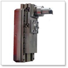
This unit is CNC-controlled and performs the various types of machining according to a previously stored program. Turret rotation is produced by a Brushless motor, while positioning is achieved through an original front-coupling system, developed by TREVISAN.
This unit is CNC-controlled and performs the various types of machining according to a previously stored program. Turret rotation is produced by a Brushless motor, while positioning is achieved through an original front-coupling system, developed by TREVISAN.
This is a CNC special purpose machine which incorporates two Modulo Equipe "1" units one opposite the other and 2 self-centering chucks, suitable for clamping special shafts.
These units allow to work each individual part on both sides simultaneously and to perform turning operations by means of CNC rotary-tool turning heads, as well as all types of drillingtapping jobs.
The bed and self-centering chucks are made of electro-welded metal plate, subjected to a stress-relieving treatment.
TheFacing head is integrated into the headstock above the Main Spindle.The Position of the Facing Head is important in context of covering the diameter range. The Main Spindle slides inside the headstock, allowing the Facing head to rotate for its full range from Zero to Maximum diameter of its Model designed. The “U” axis travel varies for each Model. Please see the Technical sheet for details.
TheFacing head is integrated into the headstock above the Main Spindle.The Position of the Facing Head is important in context of covering the diameter range. The Main Spindle slides inside the headstock, allowing the Facing head to rotate for its full range from Zero to Maximum diameter of its Model designed. The “U” axis travel varies for each Model. Please see the Technical sheet for details.
This machine is equipped with Brushless motors and cross-roller guide shoes.
This machine incorporates 3 modules with 6-position turrets, using 2 modulo equipe "2" horizontal units, with 22kw spindle motor, and 1 modulo equipe "1" vertical unit, with 18kw spindle motor.
It comes complete with 2-station pallet changer, fitted with self-centering gripping jaws.
This tool changer and tool magazine are mounted on the side of the column thus enabling tool changes to be performed at any position along the X axis. The tools are exchanged automatically by means of the two hand hydraulic manipulator. The TG2000 tool holder system was specially developed by GT Trevisan and has a unique patent. Any previous tool is removed and stored into whichever magazine it came from, after which a tool automatically selected from the magazine is moved to either of the two high torque head positions or to the ram spindle. The magazine will always take the shortest path to find the next tool, and searching can be performed during machining operations. A TG2000 tool holder base is supplied as standard for each magazine position. Extended magazine tool capacity can be supplied on request. As a standard TG 2000 tool holders will be supplied equal to the number of Magazine capacity selected.
This tool changer and tool magazine are mounted on the side of the column thus enabling tool changes to be performed at any position along the X axis. The tools are exchanged automatically by means of the two hand hydraulic manipulator. The TG2000 tool holder system was specially developed by GT Trevisan and has a unique patent. Any previous tool is removed and stored into whichever magazine it came from, after which a tool automatically selected from the magazine is moved to either of the two high torque head positions or to the ram spindle. The magazine will always take the shortest path to find the next tool, and searching can be performed during machining operations. A TG2000 tool holder base is supplied as standard for each magazine position. Extended magazine tool capacity can be supplied on request. As a standard TG 2000 tool holders will be supplied equal to the number of Magazine capacity selected.
TheFacing head is integrated into the headstock above the Main Spindle.The Position of the Facing Head is important in context of covering the diameter range. The Main Spindle slides inside the headstock, allowing the Facing head to rotate for its full range from Zero to Maximum diameter of its Model designed. The “U” axis travel varies for each Model. Please see the Technical sheet for details. The Facing diameter of the U axis slide is controlled by CNC command. The slide has more than one tool mounting positions from Model DS 450 for diameter flexibility this helps to cover the entire Range of the Diameters from minimum to Maximum diameters and Tools are loaded automatically from the tool magazine to one of thefirst or secondor thirdmounting positions. The Tool mounted on Facing Head can be used for single-point facing, boring, turning and threading operations. Standard tooling is employed at any programmed diameter to rough and finish complex internal and external profiles. Extra-large tools can be loaded automatically from a tool rack or spare pallet station, such as very long and heavy angle head attachments. The turning speed is fully programmable with constant surface speed control as on a conventional CNC lathe.
Standard flood coolant comes from the nozzles at the top of the headstock, but as an extra option, coolant is supplied through the facing head and any of the tool holders directly to the tool insert, which greatly improves tool life and surface finish.Due to the growing demand of Surface Finish inside the bores under options is available “Coolant through Facing Head”.
TheFacing head is integrated into the headstock above the Main Spindle.The Position of the Facing Head is important in context of covering the diameter range. The Main Spindle slides inside the headstock, allowing the Facing head to rotate for its full range from Zero to Maximum diameter of its Model designed. The “U” axis travel varies for each Model. Please see the Technical sheet for details. The Facing diameter of the U axis slide is controlled by CNC command. The slide has more than one tool mounting positions from Model DS 450 for diameter flexibility this helps to cover the entire Range of the Diameters from minimum to Maximum diameters and Tools are loaded automatically from the tool magazine to one of thefirst or secondor thirdmounting positions. The Tool mounted on Facing Head can be used for single-point facing, boring, turning and threading operations. Standard tooling is employed at any programmed diameter to rough and finish complex internal and external profiles. Extra-large tools can be loaded automatically from a tool rack or spare pallet station, such as very long and heavy angle head attachments. The turning speed is fully programmable with constant surface speed control as on a conventional CNC lathe.
TheFacing head is integrated into the headstock above the Main Spindle.The Position of the Facing Head is important in context of covering the diameter range. The Main Spindle slides inside the headstock, allowing the Facing head to rotate for its full range from Zero to Maximum diameter of its Model designed. The “U” axis travel varies for each Model. Please see the Technical sheet for details. The Facing diameter of the U axis slide is controlled by CNC command. The slide has more than one tool mounting positions from Model DS 450 for diameter flexibility this helps to cover the entire Range of the Diameters from minimum to Maximum diameters and Tools are loaded automatically from the tool magazine to one of thefirst or secondor thirdmounting positions. The Tool mounted on Facing Head can be used for single-point facing, boring, turning and threading operations. Standard tooling is employed at any programmed diameter to rough and finish complex internal and external profiles. Extra-large tools can be loaded automatically from a tool rack or spare pallet station, such as very long and heavy angle head attachments. The turning speed is fully programmable with constant surface speed control as on a conventional CNC lathe.
TheFacing head is integrated into the headstock above the Main Spindle.The Position of the Facing Head is important in context of covering the diameter range. The Main Spindle slides inside the headstock, allowing the Facing head to rotate for its full range from Zero to Maximum diameter of its Model designed. The “U” axis travel varies for each Model. Please see the Technical sheet for details. The Facing diameter of the U axis slide is controlled by CNC command. The slide has more than one tool mounting positions from Model DS 450 for diameter flexibility this helps to cover the entire Range of the Diameters from minimum to Maximum diameters and Tools are loaded automatically from the tool magazine to one of thefirst or secondor thirdmounting positions. The Tool mounted on Facing Head can be used for single-point facing, boring, turning and threading operations. Standard tooling is employed at any programmed diameter to rough and finish complex internal and external profiles. Extra-large tools can be loaded automatically from a tool rack or spare pallet station, such as very long and heavy angle head attachments. The turning speed is fully programmable with constant surface speed control as on a conventional CNC lathe.
TheFacing head is integrated into the headstock above the Main Spindle.The Position of the Facing Head is important in context of covering the diameter range. The Main Spindle slides inside the headstock, allowing the Facing head to rotate for its full range from Zero to Maximum diameter of its Model designed. The “U” axis travel varies for each Model. Please see the Technical sheet for details. The Facing diameter of the U axis slide is controlled by CNC command. The slide has more than one tool mounting positions from Model DS 450 for diameter flexibility this helps to cover the entire Range of the Diameters from minimum to Maximum diameters and Tools are loaded automatically from the tool magazine to one of thefirst or secondor thirdmounting positions. The Tool mounted on Facing Head can be used for single-point facing, boring, turning and threading operations. Standard tooling is employed at any programmed diameter to rough and finish complex internal and external profiles. Extra-large tools can be loaded automatically from a tool rack or spare pallet station, such as very long and heavy angle head attachments. The turning speed is fully programmable with constant surface speed control as on a conventional CNC lathe.
The Chucking tools hydraulic system consists of a variable displacement pump mounted on the hydraulic tank and high pressure oil is directed by means of hydraulic valves to facilitate tool unclamping, chucking, indexing, and also to power the “Y” Axis counter balance system.
The Chucking tools hydraulic system consists of a variable displacement pump mounted on the hydraulic tank and high pressure oil is directed by means of hydraulic valves to facilitate tool unclamping, chucking, indexing, and also to power the “Y” Axis counter balance system.
This is a CNC special purpose machine which incorporates two Modulo Equipe "1" units one opposite the other and 2 self-centering chucks, suitable for clamping special shafts.
The bed and self-centering chucks are made of electro-welded metal plate, subjected to a stress-relieving treatment.
This is a CNC special purpose machine which incorporates two Modulo Equipe "1" units one opposite the other and 2 self-centering chucks, suitable for clamping special shafts.
The bed and self-centering chucks are made of electro-welded metal plate, subjected to a stress-relieving treatment.
Secondary Business TypeManufacturer / Exporters / Wholesale Suppliers
Opening Hours
SUN : Closed
MON : 9:30 AM - 6:30 PM
TUE : 9:30 AM - 6:30 PM
WED : 9:30 AM - 6:30 PM
THU : 9:30 AM - 6:30 PM
FRI : 9:30 AM - 6:30 PM
SAT : 9:30 AM - 6:30 PM
Trevisan Macchine Utensilli S.p.A, incorporated in the Year 1960 & is located in Vicenza (Italy). The Manufacturing unit has a span of 15.000 sqm & have around 150 Employees. Pl visit web site www.trevimac.com S. Sridhar is the Director of of Reference Point Machines Pvt. Ltd. His experience, working under the various spectrums of the Machine Tools Industry, spans over three decades. Following his graduation, S. Sridhar worked in the Tool Room before switching to the role of service Engineer. After working as a service engineer for 15 years, for a wide range of machines, he moved into the field of sales in 1996. Since then, S. Sridhar has introduced many machines in India. In 2007 when Sridhar came into contact with Trevisan Machine Utensili S.p.A, a leader in its class of machines, the partnering of the two, was natural Trevisan Machine Utensili S.p.A, has placed service engineers Sreejesh and Mohan to provide Post-Sales & Service support. Sreejesh, with his Electro-Mechanical background, handles with ease, all the issues relating to Machine servicing and Application Engineer Mohan Perumal, with his experience in Production of Valves, ensures Trevisan Machines users are in a position to meet their production demands.