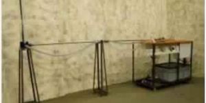
The set-up consists of different pressure measurement devices fitted in a pipe line, in which an Orifice is fitted to create the pressure difference. The student scan has good insight-of the devices. The set-up can be connected to Hydraulic Bench with flexible pipeline.
RANGE OF EXPERIMENTS
To demonstrate the working of different pressure measuring devices
To measure the pressure practically by different pressure measuring devices
FEATURES
Clear Acrylic test section
Superb Painted structure
Simple to operate & maintain
UTILITIES REQUIRED
Hydraulic Bench.
Water Supply & Drain
Electricity 1 kW, 220V AC, Single Phase
Floor Area 1.5 x 1.5
This accessory comprises a fixed speed pump assembly and independent discharge manifold interconnected by flexible tubing with quick release connectors. This auxiliary pump is intended to be used in conjunction with the basic Hydraulics Bench. The auxiliary pump is mounted on a support plinth which stands adjacent to the Hydraulics Bench primary pump.
RANGE OF EXPERIMENTS
The auxiliary pump is mounted on a support plinth which stands adjacent to the Hydraulics Bench primary pump.
Two similar pumps operating in a parallel configuration at the same speed
Two similar pumps operating in a series configuration at the same speed
UTILITIES REQUIRED
Hydraulic Bench
The apparatus consists of a glass tube with one end having bell mouth entrance; connected to a constant headwater tank, at the other end a valve is provided to vary the flow rate. The tank is of sufficient capacity to store water; a capillary tube is introduced centrally in the bell mouth for feeding dye from a small container placed at the top of tank, through PVC tubing. By varying the rate of flow, the Reynold’s number is changed. This also changes the type of flow. Visual observation of dye (Thread) will indicate the type of flow, which can be confirmed from the Reynold’s number computed. The set-up can be connected to Hydraulic Bench with flexible pipeline.
RANGE OF EXPERIMENTS
To determine the Reynold’s number and hence the type of flow either laminar or turbulent
To study transition zone
FEATURES
Clear Acrylic test section
Superb Painted structure
Simple to operate & maintain
UTILITIES REQUIRED
Hydraulic Bench.
Water Supply & Drain
Electricity 1 kW, 220V AC, Single Phase
Floor Area 1.5 x 1.5
Test SectionMaterial Clear Acrylic, compatible to 1″ Dia. Pipe.
A Pitot tube is used to measure the local velocity at a given point in the flow stress. A Pitot tube of standard design made of copper/Stainless Steel is supplied and is fixed below a vernier scale. The vernier scale is capable to measure the position of Pitot tube in transparent pipe section. The pipe has a flow control valve to regulate the flow. A manometer is provided to determine the velocity head.
RANGE OF EXPERIMENTS
To find the point velocity at the center of a tube for different flow rates of meter and calibrate the pitot tube
To find the co-efficient of Pitot tube
To study the flow distribution in a pipe and estimate the ratio of average velocity to maximum velocity at the center of pipe for different flow rates
To plot velocity profile across the cross section of pipe for different Reynold’s number.
FEATURES
Clear Acrylic test section
Superb Painted structure
Simple to operate & maintain
UTILITIES REQUIRED
Hydraulic Bench.
Water Supply & Drain
Electricity 1 kW, 220V AC, Single Phase
Floor Area 1.5 x 1.5
Pipe surge & water hammer are two related but independent phenomena which arise when fluid flowing in a pipe is accelerated or decelerated. The associated pressure transients can be damaging to pipe work or components and systems must be designed to avoid or withstand them. The equipment designed clearly demonstrates the different effects resulting from gradual or instantaneous changes in fluid velocity (created by slow and fast valve closure). Effect of initial fluid velocity can also be investigated. Pipe surge resulting from a gradual change in fluid velocity is clearly seen as fluctuating changes in head in a surge shaft. Water hammer resulting from a rapid change in fluid velocity is clearly seen as large changes in pressure monitored using a pair of transducers and indicated using an oscilloscope. The equipment comprises two SS pipes connected to a constant head tank. A service module provides the water supply to the head tank and also incorporates a volumetric tank for flow rate measurement, sump tank, circulating pump and flow control valve. Water enters the two test pipes via the constant head tank and discharges into the volumetric tank. A dump valve in the volumetric tank returns the water to the sump tank. The pipe surge test section incorporates a clear acrylic surge shaft to enable visualisation of its oscillatory characteristics to be demonstrated. A metric scale on the shaft permits the height of the oscillations to be measured. The test pipe terminates with a lever operated gate valve and separate flow control valve. The water hammer test section uses a unique fast acting valve specifically designed. Pressure transducers mounted at the fast acting valve itself and at a point along the test pipe provide analogue outputs which are fed into a signal conditioning module. The corresponding output voltage from the signal conditioning module can then be fed into a dual trace oscilloscope. Output is available from the oscilloscope. This allows the stored display to be transferred onto a suitable printer to provide a hard copy of the transient.
RANGE OF EXPERIMENTS
Demonstration of pipe surge
Determination of oscillatory characteristics of the surge shaft
Demonstration of frictional head loss between reservoir and surge shaft
Comparison between theoretical and measured pressure profiles produced by water hammer
Using a dual trace storage oscilloscope to record transient water hammer pressure profiles
Measuring the pressure profile characteristics
Determination of the velocity of sound through a fluid in a pipe
Demonstration of the effects of cavitations on subsequent cycles.
FEATURES
Clear test section for visualization of phenomena.
Superb Painted structure
Simple to operate & maintain
UTILITIES REQUIRED
Hydraulic Bench.
Water Supply & Drain
Electricity 1 kW, 220V AC, Single Phase
Floor Area 1.5 x 1.5
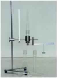
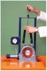
The apparatus is used to demonstrate that the pressure at the bottom of a liquid column in a vessel depends only on the height of the column but not on the shape of the vessels. The equipment consists of a tapered glass socket fitted into a base block held to a stand by a rod. The other side of the base block also has a rod holding a pivot supporting a lever. One end of the lever is a pressure disc against the bottom of the base block while the other end of the lever has a sliding weight hanger with weights. Glass vessels of different shapes can alternatively fit on the tapered glass socket. Height of water column is measured by a scale.
TECHNICAL DETAILS
Tapered glass socket with base block, rod holder, lever and pressure disc. Glass vessels: straight, offset, reduced and conical. Weight hanger and weight. Stand and a pan Dimensions / Weight: 200 x 300 x 770 mm / ca. 3.4 kg.
The whole setup is well designed and arranged in a good quality painted structure.
THE APPARATUS CONSISTS OF A GLASS TUBE WITH ONE END HAVING BELL MOUTH ENTRANCE; CONNECTED TO A CONSTANT HEADWATER TANK, AT THE OTHER END A VALVE IS PROVIDED TO VARY THE FLOW RATE. THE TANK IS OF SUFFICIENT CAPACITY TO STORE WATER; A CAPILLARY TUBE IS INTRODUCED CENTRALLY IN THE BELL MOUTH FOR FEEDING DYE FROM A SMALL CONTAINER PLACED AT THE TOP OF TANK, THROUGH PVC TUBING. BY VARYING THE RATE OF FLOW, THE REYNOLD’S NUMBER IS CHANGED. THIS ALSO CHANGES THE TYPE OF FLOW. VISUAL OBSERVATION OF DYE (THREAD) WILL INDICATE THE TYPE OF FLOW, WHICH CAN BE CONFIRMED FROM THE REYNOLD’S NUMBER COMPUTED. THE SET-UP CAN BE CONNECTED TO HYDRAULIC BENCH WITH FLEXIBLE PIPELINE.
RANGE OF EXPERIMENTS
To determine the Reynold’s number and hence the type of flow either laminar or turbulent
To study transition zon
FEATURES
Clear Acrylic test section
Superb Painted structure
Simple to operate & maintain
UTILITIES REQUIRED
Hydraulic Bench.
Water Supply & Drain
Electricity 1 kW, 220V AC, Single Phase
Floor Area 1.5 x 1.5
Channel Test Section600 x 250 x 180 mm made of stainless steel
NotchesMaterial Brass (3 Nos.)
1. Rectangular Notch
2. 45° V Notch
3. 60° V Notch
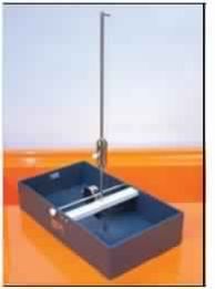
It consists of a tank provided with inlet supply diffuser, overflow outlet. Provision for fitting Orifice or Mouthpiece at the same position is provided. An arrangement is done to vary head and keep it constant at desired level. The set-up can be connected to Hydraulic Bench by flexible pipe line.
RANGE OF EXPERIMENTS
To determine the co-efficient of discharge of different orifice and Mouthpiece
FEATURES
Clear Acrylic test section
Superb Painted structure
Simple to operate & maintain
UTILITIES REQUIRED
Hydraulic Bench.
Water Supply & Drain
Electricity 1 kW, 220V AC, Single Phase
Floor Area 1.5 x 1.5
Overall DimensionsLength 350mm X Width 200mm X Overall height 475mm
This equipment allows a thorough investigation of the factors affecting the stability of a floating body. The position of the metacentre can be varied to produce stable and unstable equilibrium. The equipment consists of a rectangular floating pontoon, the centre of gravity of which can be varied by an adjustable weight which slides and can be clamped in any position on a vertical mast. A single plumb-bob is suspended from the mast which indicates the angle of heel on a calibrated scale. A weight with lateral adjustment allows the degree of heel to be varied and hence the stability of the pontoon determined.
RANGE OF EXPERIMENTS
Determining the centre of gravity of the pontoon
Determining the metacentric height and from this the position of the metacentre for the pontoon
Varying the metacentric height with angle of heel
FEATURES
Light weight test section
Compact & stand alone set up
Simple to operate & maintain
UTILITIES REQUIRED
Hydraulic Bench.
Water Supply & Drain
Electricity 1 kW, 220V AC, Single Phase
Floor Area 1.5 x 1.5
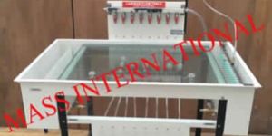
Overall DimensionsL x W x H: 1400 x 810 x 1310mm, Weight: approx. 140 kg
The laminar, two-dimensional flow is a good approximation of the flow of ideal fluids: the potential flow. All physical systems described with the Laplace equation can be demonstrated with potential flow. This includes heat flow and potential theory, for example. The core element of the trainer is a classical Hele-Shaw cell with additional water connections for sources and sinks. The laminar, two-dimensional flow is achieved by water flowing at low speed in a narrow gap between two parallel glass plates. The flow generated in this way is non-vertical and can be regarded as potential flow. The streamlines are displayed in colour by introducing a contrast medium (ink). In experiments an interchangeable model is inserted into the flow, such as a cylinder, guide vane profile or nozzle contour. Sources and sinks are generated via eight water connections in the bottom glass plate. The streamlines can be clearly observed on the screened glass during flow around and through. A flow straightener ensures consistent and low turbulence flow. The water flow and the amount of contrast medium added can be adjusted by using valves. The water connections are also activated by valves and can be combined as required. The well-structured instructional material sets out the fundamentals and provides a step-by-step guide through the experiments.
RANGE OF EXPERIMENTS
Flow around drag bodies: cylinder, guide vane profile, square, rectangle
Flow through models: nozzle contour, discontinuous constriction or enlargement
Flow separation, flow with 90° redirection
FEATURES
Clear test section for visualization of phenomena.
Superb Painted structure
Simple to operate & maintain
UTILITIES REQUIRED
Hydraulic Bench.
Water Supply & Drain
Electricity 1 kW, 220V AC, Single Phase
Floor Area 1.5 x 1.5
Number of guide vanes6, adjustable from fully open to fully closed
Range of spring balances0 to 10 N x 0.1 N
Range of Bourdon gauge0 to 2 bar
This demonstration turbine provides a simple low cost introduction to the Kaplan (axial flow) turbine showing its construction, operation and performance. A tapering, spiral shaped volute conveys water to the runner via a ring of guide vanes that are adjustable in angle to vary the flow through the turbine. Water enters the runner tangentially at the periphery, flows axially outward through the blades towards the hub then exits axially via a draft tube. Power generated by the turbine is absorbed by a Prony friction brake consisting of a pair of spring balances attached to a brake belt that is wrapped around a pulley wheel driven by the runner. The load on the turbine is varied by tensioning both spring balances which increases the friction on the pulley wheel. Brake force is determined from the difference in the readings on the two spring balances and the torque calculated from the product of this force and the pulley radius. The head of water entering the turbine is indicated on a Bourdon gauge and the speed of rotation is measured using a non-contacting tachometer (not supplied).The volute of the Kaplan turbine incorporates a transparent front cover for clear visualisation of the runner and guide vanes.
RANGE OF EXPERIMENTS
Determining the operating characteristics, i.e. power, efficiency and torque, of a Francis Turbine at various speeds and guide vane opening
UTILITIES REQUIRED
Hydraulic Bench
Water Supply & Drain
Electricity 1 kW, 220V AC, Single Phase
Floor Area 1.5 x 1.5 m
Stainless Steel EnclosureHaving of opposite sides made of glass.
The setup consists of a clear fabrication section. Water is fed through a nozzle and discharged vertically to strike a target carried on a stem, which extends through the cover. A weight carrier is mounted on the upper end of the stem. The dead weight of the moving parts is counter balanced by a compression spring. The vertical force exerted on the target plate is measured by adding the weights supplied to the weight pan until the mark on the weight pan corresponds with the level gauge. A total of two targets are provided, a flat plate and a hemispherical cup.
RANGE OF EXPERIMENTS
To measure the force developed by a jet of water impinging upon a stationary object and comparison with the forces predicted by the momentum theory.
FEATURES
Clear Acrylic test section
Superb Painted structure
Simple to operate & maintain
UTILITIES REQUIRED
Hydraulic Bench.
Water Supply & Drain
Electricity 1 kW, 220V AC, Single Phase
Floor Area 1.5 x 1.5
If flowing water is suddenly brought to rest in a long pipe, a phenomena known as water hammer occurs, wherein a pressure wave travels along the pipe. This principle is used in the hydraulic ram to pump water.The Hydraulic Ram comprises an acrylic base incorporating pulse and non-return valves and a supply reservoir on a stand which is fed by the Hydraulics Bench. An air vessel above the valve chamber smooth’s cyclic fluctuations from the ram delivery. The weights supplied may be applied to the pulse valve to change the closing pressure and hence the operating characteristics.
RANGE OF EXPERIMENTS
Establishing flow/pressure characteristics and determining efficiency of the hydraulic ram
UTILITIES REQUIRED
Hydraulic Bench
RAMSize 50 x 15mm, Supply Head 1 m approx, Delivery Head 10 m (Max.)
Air VesselSuitable capacity MOC SS
Delivery lineFor RAM, Dia 50 mm length 1 m.
PumpCapacity FHP, Crompton/Sharp / Hero make
Supply TankCapacity 70 Ltrs.
Overhead TankCapacity 40 Ltrs.
Measuring TankFor useful water 1000ml (Measuring Cylinder) For Waste water 20ltr SS tank fitted with Piezometer tube & scale
PipingGI / PVC
Stop WatchElectronic
Control PanelWith required electrical instrumentation
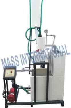
The setup is designed to study the Hydraulic Ram. Hydraulic Ram is used for pump little quantity of water to high head from a large quantity of water available at low head. It works on a principle of water hammer stating that “when flowing water is suddenly stopped in a long pipe a pressure wave travels along the pipe creating an effect of water hammer”. Set up consists of a pipe section fitted with a pulse valve and non-return valve, a supply reservoir on a stand which is connected to an overhead tank, an air vessel above the valve chamber smoothes cyclic fluctuations from the Ram delivery. Different pressure may be applied to the pulse valve to change the closing pressure and hence the operating characteristic. The flow rate of useful and waste water is measured using measuring tank and stop watch provided. Pressure gauge is connected for the purpose of measurement.
RANGE OF EXPERIMENTS
To find out discharge of useful & waste water.
To find out the efficiency of the Hydraulic ram.
FEATURES
Closed loop water circulation
Compact & stand alone set up
Stainless Steel tanks and wetted parts
Superb Painted structure
Simple to operate & maintain
UTILITIES REQUIRED
Electric supply 230 +/- 10VAC,50Hz,1 phase
Water supply Tap water connection ½” BSP
Distilled water @ 80 liters (optional)
Floor Area 1.5 x 1.5
Measuring Tank Capacity 40 Ltrs. MOC SS / MS powder coated
Sump TankCapacity 120 Ltrs MOC SS / MS powder coated
Pipe fittingsMOC GI/PVC
Stop WatchElectronic
Control PanelOn/Off Switch, Mains Indicator, etc.
DESCRIPTION
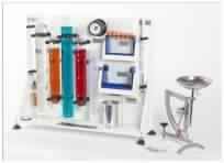
The present set-up is a self-contained, water re-circulating unit provided with a top tray and a sump tank. Various hydraulics experiments can be conducted on this set-up. A Centrifugal Pump is fitted for water circulation. Flow control valve and by-pass valve are fitted in water line to conduct the experiment on different flow rates. Flow rate of water is measured with the help of measuring tank and stop watch. Water collected on the top tray from experimental set-up, drains and return to sump tank.
EXPERIMENTS
Following experiments can be carried out with common basic table, with separate experimental set-ups (supplied at extra cost), which can be connected to hydraulic bench with flexible pipe:
Bernoulli's Theorem Apparatus
Orifice and Mouth Piece
Flow measurement by Venturimeter
Flow measurement by Orifice meter
Losses due to Friction in Pipe Lines
Losses in Pipe fittings and pipe bends
Tilting Flume
Reynolds’s Number study
Flow over notches
Impact of Jet on Vanes
Study of Pressure Measurement
Pitot Static Tube
Forced Vortex Apparatus
Free Vortex Apparatus
FEATURES
Closed loop water circulation
Compact & stand alone set up
Stainless Steel tanks
Superb Painted structure
Simple to operate & maintain
UTILITIES REQUIRED
Water Supply & Drain
Electricity 1 kW, 220V AC, Single Phase
Floor Area 1.5 x 1.5 m
DESCRIPTION
The present set-up is a self-contained, water re-circulating unit provided with a top tray and a sump tank. Various hydraulics experiments can be conducted on this set-up. A Centrifugal Pump is fitted for water circulation. Flow control valve and by-pass valve are fitted in water line to conduct the experiment on different flow rates. Flow rate of water is measured with the help of measuring tank and stop watch. Water collected on the top tray from experimental set-up, drains and return to sump tank.
EXPERIMENTS
Following experiments can be carried out with common basic table, with separate experimental set-ups (supplied at extra cost), which can be connected to hydraulic bench with flexible pipe:
Bernoulli's Theorem Apparatus
Orifice and Mouth Piece
Flow measurement by Venturimeter
Flow measurement by Orifice meter
Losses due to Friction in Pipe Lines
Losses in Pipe fittings and pipe bends
Tilting Flume
Reynolds’s Number study
Flow over notches
Impact of Jet on Vanes
Study of Pressure Measurement
Pitot Static Tube
Forced Vortex Apparatus
Free Vortex Apparatus
FEATURES
Closed loop water circulation
Compact & stand alone set up
Stainless Steel tanks
Superb Painted structure
Simple to operate & maintain
UTILITIES REQUIRED
Water Supply & Drain
Electricity 1 kW, 220V AC, Single Phase
Floor Area 1.5 x 1.5 m
PumpDouble acting, Single Cylinder
Capacity 1 HP, Speed 250 RPM (max.), Head 5kg/cm2 (max.)
DriveHM 04 AC : AC motor with step cone pulley arrangement
HM 04 DC : DC motor with DC drive for variable speed.
Supply TankCapacity 50 Ltrs. MOC SS
Measuring TankCapacity 30 Ltrs. MOC SS fitted with Piezometer Tube & scale
Pressure GaugeBourdon Type
PipingGI / PVC
Stop WatchElectronic
Control PanelWith required electrical instrumentation
RPM Indicator with Proximity Sensor
Electronic Energy Meter
On /Off switch Main indicator etc.
The setup is designed to study the performance of gear pump. Set up consists of a gear pump having a pair of meshed gears coupled with electrical motor, supply tank, measuring tank & pipe fittings for closed loop oil circulation. Pressure and Vacuum gauges are connected on delivery and suction side of pump for the purpose of measurement. The flow rate of water is measured using measuring tank and stop watch provided.
RANGE OF EXPERIMENTS
To determine overall efficiency and pump efficiency of the centrifugal pump.
To plot Head vs. Discharge, Pump efficiency vs. Discharge
FEATURES
Closed loop water circulation
Compact & stand alone set up
Stainless Steel tanks and wetted parts
Superb Painted structure
Simple to operate & maintain
UTILITIES REQUIRED
Electric supply 230 +/- 10VAC,50Hz,1 phase
Water supply Tap water connection ½” BSP
Distilled water @ 80 liters (optional)
Floor Area 1.5 x 1.5
The experimental set up consist of a circular transparent cylindrical tank in which four circumferential jets have been placed along the circumference of the cylinder near its bottom which helps in the formation of free vortex. (It is assumed that the torque exerted by these jets is negligible). The Orifice is provided with a reducing bush so that a reduced diameter can be investigated. The plate can also be rotated with the help of a variable speed motor so that the cylinder rotates about its vertical axis with the help of a V belt and forced vortex is formed. Conditions were allowed to steady state and the depth of flow at any particular point was observed not to change over a period of time. The experimental procedure involves measurement of the resulting free surface that represents the variation of the sum of the pressure head and datum head.
RANGE OF EXPERIMENTS
To plot the surface profile of a free and forced vortex by measurement of the surface profile coordinates and to show that total energy is constant throughout vortex.
FEATURES
Clear Acrylic test section
Superb Painted structure
Simple to operate & maintain
UTILITIES REQUIRED
Hydraulic Bench.
Water Supply & Drain
Electricity 1 kW, 220V AC, Single Phase
Floor Area 1.5 x 1.5
Number of guide vanes6, adjustable from fully open to fully closed
Range of spring balances0 to 10 N x 0.1 N
Range of Bourdon gauge0 to 2 bar
This demonstration turbine provides a simple low cost introduction to the Francis inward flow reaction turbine showing its construction, operation and performance. A tapering, spiral shaped volute conveys water to the runner via a ring of guide vanes that are adjustable in angle to vary the flow through the turbine. Water enters the runner tangentially at the periphery, flows radially inwards through the blades towards the hub then exits axially via a draft tube. Power generated by the turbine is absorbed by a Prony friction brake consisting of a pair of spring balances attached to a brake belt that is wrapped around a pulley wheel driven by the runner. The load on the turbine is varied by tensioning both spring balances which increases the friction on the pulley wheel. Brake force is determined from the difference in the readings on the two spring balances and the torque calculated from the product of this force and the pulley radius. The head of water entering the turbine is indicated on a Bourdon gauge and the speed of rotation is measured using a non-contacting tachometer (not supplied). The volute of the Francis turbine incorporates a transparent front cover for clear visualisation of the runner and guide vanes.
RANGE OF EXPERIMENTS
Determining the operating characteristics, i.e. power, efficiency and torque, of a Francis Turbine at various speeds and guide vane opening
UTILITIES REQUIRED
Hydraulic Bench
Overall DimensionsHeight: 1250mm (maximum to top of level gauge) X Width: 425mm X Depth: 150mm
Max depth inside reservoir574mm/td>
Inside diameter of reservoir100mm
Scale length of manometer tubes460mm
Manometer tubes incorporated1x ‘U’ tube
2x Vertical parallel tubes
1x Vertical tube with varying cross section
1x Vertical tube with pivot enabling operation at three different inclinations
The Setup is designed to demonstrate the properties of Newtonian fluids and their behaviour under hydrostatic conditions (fluid at rest). This enables students to develop an understanding and knowledge of a wide range of fundamental principles and techniques, before studying fluids in motion. These include the use of fluids in manometers to measure pressure and pressure differences in gases and liquids. Some simple exercises are included to show how the behaviour of a fluid changes when flow is involved and the relevance of concepts such as frictional losses. The apparatus is constructed from PVC and clear acrylic and consists of a vertical reservoir containing water that is connected to a series of vertical manometer tubes. These tubes can be used individually or in combination for the different demonstrations of hydrostatic principles and Manometry. One tube includes changes in cross section to demonstrate that the level of a free surface is not affected by the size or the shape of the tube. The right hand manometer tube is separate from the other tubes and incorporates a pivot and indexing mechanism at the base that enables this tube to be inclined at fixed angles of 5°, 30°, 60° and 90° (vertical). The reservoir incorporates a hook and point gauge with Vernier scale, mounted through the lid, that enables large changes in level to be measured with better precision than a simple scale. A vertical transparent piezometer tube through the lid of the reservoir enables the static head above the water in the reservoir to be observed when the air space above the water is not open to atmosphere. Connections at the top of the reservoir and each of the manometer tubes enables a syringe to be connected using flexible tubing that permits the static pressure of the air to be varied positively or negatively as required for the various demonstrations. The syringe and flexible tubing for filling the equipment etc. are stored at the rear of the apparatus when not in use for convenience. A small flow can be induced through the interconnecting pipework between the various manometer tubes to provide a simple but clear demonstration of the effect of friction created by the motion of the fluid. This is useful to the student before performing demonstrations using more advanced Fluid Dynamics accessories. The equipment is designed to demonstrate the basic principles of hydrostatics and Manometry using water for safety and convenience. The use of a safe, soluble food dye in the water makes observation of the level changes clearer without affecting the operation of the apparatus. Alternative liquids, with different densities, can be used in the ‘U’ tube manometer if required to extend the range of the demonstrations.
RANGE OF EXPERIMENTS
Demonstrating the behaviour of liquids at rest (Hydrostatics)
Showing that the free surface of a liquid is horizontal and independent of cross section
Measuring liquid level using a scale and the effect of parallax
Measuring small changes in liquid level using a micro manometer
Measuring changes in liquid level using a Vernier hook and point gauge
Using a single piezometer / manometer tube to measure head
Using manometer tubes to measure differential pressure
Using an inclined manometer to measure small pressure differences
Using a ‘U’ tube manometer to measure pressure differences in a gas (air over liquid)
Using an inverted pressurized ‘U’ tube manometer to measure pressure differences in a liquid
Using liquids with different densities to change the sensitivity of a ‘U’ tube manometer
Demonstrating the effect of trapped air on the accuracy of a manometer
Demonstrating the effect of flowing liquid (friction in a fluid created by motion)
COMPNENTS
Demonstrates the basic principles of hydrostatics and Manometry
Includes vertical tube with variable cross section, Scale length 460mm
Includes demonstrations of the following types of manometer:
Single piezometer manometer tube, Scale length 460 mm
Inclined manometer with inclinations of 5°, 30°, 60° and 90° (vertical)
Enlarged limb-manometer
U’ tube manometer (air over liquid), Scale length 460 mm
‘U’ tube manometer (liquid over liquid), Scale length 460 mm
Inverted pressurized ‘U’ tube manometer, Scale length 460 mm
Level measurement using Vernier hook and point gauge, Range 0 to 150 mm with 0.1 mm resolution
Allows the effect of friction to be demonstrated when fluid is in motion
This apparatus provides an introduction to the fundamental properties of liquids that affect their behavior in practical applications.A clear understanding about the physical properties of fluids is essential before studying the behavior of fluids in static or dynamic applications.This apparatus introduces students to the following properties of fluids: Density and relative density (specific gravity) Viscosity Capillarity – capillary elevation between flat plates and in circular tubes Buoyancy (Archimedes principle) Atmospheric pressure The apparatus consists of a collection of components that demonstrate individual fluid properties. The components are stored on a common support frame with circular spirit level and adjustable feet for leveling. The apparatus is designed to stand on a suitable bench top where some of the components can be operated independent from the support frame. A freestanding dual scale lever balance is also supplied to support several of the demonstrations.
RANGE OF EXPERIMENTS
Measuring fluid density and relative density (specific gravity) of a liquid using a universal hydrometer
Measuring fluid density and relative density (specific gravity) of a liquid using a pycnometer (density bottle)
Observing the effect of capillary elevation between flat plates
Measuring the effect of capillary elevation inside capillary tubes
Verifying Archimedes principle using a brass bucket & cylinder with a lever balance
Measuring atmospheric pressure using an aneroid barometer
COMPNENTS
2x Hydrometer jars (clipped to stand)
1x Universal hydrometer (in protective housing)
2x Falling sphere viscometer tubes (clipped to stand)
1x Plastic storage box containing steel spheres
1x Spirit filled glass thermometer (in protective housing)
1x Direct reading aneroid barometer (fixed to stand)
1x Parallel plate capillary apparatus
1x Capillary tube apparatus with 6 tubes of varying size
1x Archimedes apparatus comprising displacement vessel, machined bucket & matching cylinder
1x 50 ml density bottle
1x 250 ml plastic measuring cylinder
1x 600 ml glass beaker
1x Dual scale lever balance, adapted for use with Archimedes apparatus
Overall DimensionsHeight: 1250mm (maximum to top of level gauge) X Width: 425mm X Depth: 150mm
Max depth inside reservoir574mm/td>
Inside diameter of reservoir100mm
Scale length of manometer tubes460mm
Manometer tubes incorporated1x ‘U’ tube
2x Vertical parallel tubes
1x Vertical tube with varying cross section
1x Vertical tube with pivot enabling operation at three different inclinations
The unit consists of a tubular steel framework which supports the network of pipes and fittings for test. Pipe friction experiments are carried out using four smooth pipes of different diameters, plus one roughened pipe. Short samples of each size test pipe are provided loose so that the students can measure the exact diameter and determine the nature of the internal finish. A system of isolating valves is provided whereby the pipe to be tested can be selected without disconnecting or draining the system. A selection of pipe fittings and valves are fitted around the network and are fitted with pressure tapings. A clear acrylic pipe section incorporates a Venturi, orifice plate and Pitot tube. Pressure tappings are fitted with quick action self-sealing connections. Probe attachments are provided with tubing so that any pair of pressure tapings can be rapidly connected to appropriate instrumentation, eg. a manometer
RANGE OF EXPERIMENTS
Confirming the relationship between head loss due to fluid friction and velocity for flow of water
Determining the head loss associated with flow through a variety of standard pipe fittings
Determining the relationship between pipe friction coefficients and Reynolds’ number for flow through a pipe with roughened bore
Demonstrating the application of differential head devices in the measurement of flow rate and velocity
Providing practical training of pressure measurement techniques
Models:broad crested weir
narrow crested weir
symmetrical aerofoil
asymmetrical aerofoil
small cylinder
large cylinder
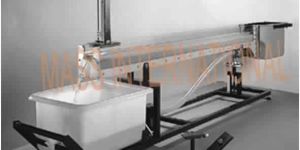
The channel consists of a clear acrylic working section of large depth to width ratio incorporating undershot and overshot weirs at the inlet and discharge ends respectively. Water is fed to the streamlined channel entry via a stilling tank to reduce turbulence. Water discharging from the channel is collected in the volumetric tank of the Hydraulics Bench and returned to the sump for recirculation. A dye injection system incorporated at the inlet to the channel permits flow visualization in conjunction with a graticule on the rear face of the channel. Models supplied with the channel include broad and sharp crested weirs, large and small diameter cylinders and symmetrical and asymmetrical aerofoil’s which, in conjunction with the inlet and discharge weirs, permit a varied range of open channel and flow visualization demonstrations.
RANGE OF EXPERIMENTS
Demonstrating basic phenomena associated with open channel flow
Visualization of flow patterns over or around immersed objects
FEATURES
Clear Acrylic test section
Superb Painted structure
Simple to operate & maintain
The Demonstration Pelton Turbine provides a simple low cost introduction to turbine performance.This accessory comprises a miniature Pelton wheel with spear valve arrangement mounted on a support frame which locates on the Hydraulics Bench top channel. Mechanical output from the turbine is absorbed using a simple friction dynamometer. Pressure at the spear valve is indicated on a remote gauge. A non-contacting tachometer (not supplied) may be used to determine the speed of the Pelton wheel.Basic principles of the Pelton turbine may be demonstrated and, with appropriate measurements, power produced and efficiency may be determined.
RANGE OF EXPERIMENTS
Determining the operating characteristics, i.e. power, efficiency and torque, of a Pelton turbine at various speeds
UTILITIES REQUIRED
Hydraulic Bench
Secondary Business TypeManufacturer / Exporters / Wholesale Suppliers
Opening Hours
SUN : Closed
MON : 9:30 AM - 6:30 PM
TUE : 9:30 AM - 6:30 PM
WED : 9:30 AM - 6:30 PM
THU : 9:30 AM - 6:30 PM
FRI : 9:30 AM - 6:30 PM
SAT : 9:30 AM - 6:30 PM
Mass International is Retailer of Hydraulic Bench, BERNOULLI'S THEOREM DEMONSTRATION, Fluid Mechanics Apparatus, ORIFICE AND MOUTHPIECE, IMPACT OF JET ON VANES, REYNOLDS APPARATUS (HORIZONTAL), OSBORNE REYNOLDS DEMONSTRATION (VERTICAL), STUDY OF PRESSURE MEASUREMENT, Free And Force Vortex Apparatus, CAVITATION DEMONSTRATION from Ambala, Haryana.