Description: The Window AC test rig is designed and manufactured such that the students can understand construction and working of a window type air conditioner and conduct the trial on it to evaluate performance of the same. The window AC is fixed in a rigid angle frame, with its cover cut half open to reveal the internal parts of the AC. The required pressure and temperature tapings are drawn for measurement of pressures and temperatures at salient points. Energy meter is provided for recording compressor energy consumption. A sling psychrometer is provided for measurement of inlet and outlet Dry-bulb & wet bulb temperature. With the help of manometer, velocity of air and consequently the flow rate of air can be determined.
Description: The Window AC test rig is designed and manufactured such that the students can understand construction and working of a window type air conditioner and conduct the trial on it to evaluate performance of the same. The window AC is fixed in a rigid angle frame, with its cover cut half open to reveal the internal parts of the AC. The required pressure and temperature tapings are drawn for measurement of pressures and temperatures at salient points. Energy meter is provided for recording compressor energy consumption. A sling psychrometer is provided for measurement of inlet and outlet Dry-bulb & wet bulb temperature. With the help of manometer, velocity of air and consequently the flow rate of air can be determined.
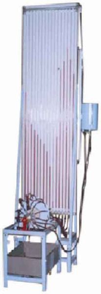
This is an open circuit Wind Tunnel which provides a region of controlled airflow into which models can be inserted. The propulsion is provided by a fan at downstream of working section. The tunnel consists of bell mouth shaped entry to guide the air smoothly into settling chamber consisting of honeycomb and nylon mesh screens which filters and stabilizes the air flow. This follows working section or test section where various models can be tested. Two windows with acrylic sheet one each on either side will be provided for visual observation. Working section is followed by diffuser section, which reduces the dynamic pressure at the exit. A three -blade fan coupled with D.C variable speed motor is used to produce desired wind velocity. A thyristorised motor control is used for smooth variation of air velocity.
SPECIFICATIONS :
Type : Open type Wind Tunnel.
Test Section : 300mm x 300mm x 1000 mm. long with two Perspex windows.
Blower Fan : 3 /10 blades M.S. /nylon fan.
Motor : 7.5 HP D.C shunt motor, 1500rpm.
Speed Controller : 3 phase, thyristor controller to give smooth Speed control.
Air Velocity : In test section - 1 to 30 m/sec.
Duct : Manufactured out of ms sheet.
Length of Tunnel : 4/5 meter.
INSTRUMENTATION:
LIFT & DRAG INDICATOR -
Lift - Display: - 3 ½ digit, Least count: - 0.1 kg Range : - 20 kg
Drag - Display: - 3 ½ digit, Least count: - 0.1 kg Range : - 20 kg
MANOMETERS: -
Multitube Manometer : 500mm. Height, 500mm, width, 15 pvc tubes, 6mm, dia,
Pitot tube : 100cm. Long chrome plated pipe tube, 3/8” dia.
WOODEN MODELS :-
Aerofoil:
Symmetrical
Unsymmetrical. 150mm, width and 150mm.long with 15 piezometric tapping with 0-360 degree protractor.
Cylindrical Model: 75mm, dia., 150mm long with piezometric tapping and 0-360 degree protractor.
Spherical Model: - 65mm, dia.
EXPERIMENTATION :-
To study pressure distribution around a) Aerofoil b) Cylinder.
To measure lift & drag on airfoil model, cylinder model & sphere model.
The apparatus consists of a base upon which bearing holders and drive motor can be mounted. Different bearings can be fitted in bearing block to have different end conditions, such as, both end fixed, one end fixed, one end etc. free. A variable speed motor along with speed controller is provided to drive the shaft. The unit is useful to demonstrate the phenomenon of Whirling of Shaft with single rotor. As this test is destructive, after the test shaft can not be used again, hence this unit only demonstrates the principle.
The apparatus consists of a base upon which bearing holders and drive motor can be mounted. Different bearings can be fitted in bearing block to have different end conditions, such as, both end fixed, one end fixed, one end etc. free. A variable speed motor along with speed controller is provided to drive the shaft. The unit is useful to demonstrate the phenomenon of Whirling of Shaft with single rotor. As this test is destructive, after the test shaft can not be used again, hence this unit only demonstrates the principle.
VORTEX TUBE TEST RIG
Description: The Vortex Tube is one of the non- conventional methods of cooling which has no moving parts. It requires only source of compressed air. Through this tube, when air is admitted at high pressure, from one end, hot sir is discharged and from the other end, cold air comes out. The test rig is designed such that all the performance can be evaluated.
Specifications subject to change without any notification.
LIST OF EXPERIMENTS:
To understand the principle of working Vortex Tube.
To evaluate Adiabatic Efficiency of the system.
To evaluate C.O.P. of the system.
To find out Refrigeration Effect per kg of air supplied.
MODELAEVX-01
Material of construction of the vortex tube
Brass /GI/ SS tube With inlet nozzle and diaphragm
Temperature measurement
Digital led display provided
Pressure measurement
Dial type pressure gauge provided or manometer
Arrangement for air flow measurement
Provided.
Air flow variation
Valve provided
General arrangement
Integral unit mounted on suitable panel.
Supply
Compressed air supply at 10 bar
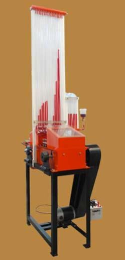
This set up has been designed to perform and verify the principles involved in study of vibrations. It consists of a basic frame and various components and sub assemblies designed for quick changeover and easy assembly of number of experiments in vibrations. A speed controller unit is provided for forced vibration experiments.
With this unit following experiments can be conducted –
Pendulum Experiments
For Pendulum a sub frame is attached to upper beam. Two Chucks and Hardened V guide is provided for carrying experiments.
Experiment - 1 - Simple Pendulum
To verify the relation
L
T = 2 p
g
and plot graph T² Vs. L
Experiment - 2 - Compound Pendulum
To verify the relation
K² + (OG)²
T = 2 p
g (OG)
To determine the radius of gyration and equivalent length of compound pendulum.
Experiment - 3 - Bi-filler Suspension
( Tortional Oscillations) To determine the radius of gyration of body about the center of gravity by using relation
K L
T = 2 p
a g
Experiment - 4 - Longitudanal Vibration
To verify the relation -
W
T = 2 p
Km x g
and plot graph T² Vs. W
Experiment - 5 - Equivalent spring mass system
Study of un damped natural vibrations of beam pivoted at one end supported by tension spring at the other end.
Experiment - 6 - Equivalent spring mass system
Study of undamped natural vibration of beam pivoted at one end supported by tension spring at the other end to plot a graph of amplitude verses frequency.
Experiment - 7 - Single Rotor
To verify the relation -
I
T = 2 p
Kt
and study the relationship between the periodic time and shaft length.
Experiment - 8 - Two Rotor
To verify the relation -
I
A
+ I
B
T = 2
Kt (I
A
+ I
B
)
and plot a graph F Vs. 1/ I1
Experiment - 9 - Single Rotor with viscous damping
To find out the damping coefficient Ct for various depths of damping drum (Immersed in oil) and to plot a graph of damping torque Vs. depth of damping drum.
Experiment - 10 - Dunkerley's Rule
To find out the natural frequency of a beam with and without load and to verify the Dunkerley's Rule.
Experiment - 11 - Forced Vibrations
To study the forced vibrations for various amount of damping and to plot a graph of amplitude verses frequency. Following accessories will be supplied along with unit. - Exciter unit with FHP motor and controller. Ordinary strip chart recorder. Damper with an arrangement for changing damping.
The test rig consists of a GI pipe line fitted with a set of gunmetal venturimeter and orificemeter of size 25mm(1"), and of d/D Ratio = 0.6. The flow meters are provided with pressure tappings with quick change over cocks. A differential manometer (without mercury) is provided to measure the pressure difference across the venturimeter/orificemeter to be tested. The pressure tappings are connected to a common manifold which in turn is connected to the manometer. A strong iron stand is provided for supporting the pipe lines. A stop watch and an M.S. collecting tank of size 90 liters. with a gauge glass scale fitting, a drain valve and a bend are provided to measure the actual flow rate.
A 220 volt AC, 0.5 HP, single phase monoblock ISI pumpset with suitable pipe fittings, strainer foot valve, and switch is provided to supply water to the test rig.
A sump tank of size 200 liters with suitable drain is provided to store the water. A strong iron stand fitted with wheels supports the complete test rig. The unit is moveable. All tanks are provided with FRP lining for total rust protection.
·TEMPERATURE INDICATORDIGITAL INDICATOR AT THE SALIENT POINTS
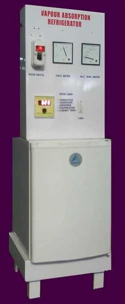
“Vapour Absorption Refrigerator” earlier known as “Electrolux” refrigerator is an self contained refrigerator working on absorption technology. In the absence of a compressor or pump, the circulation takes place by density difference. The system is pre-charged with three fluids namely water, ammonia and hydrogen. Hydrogen is used as an “inert gas” and does not undergo any phase change and heat transfer processes. Its purpose is to keep the pressure of the system constant. It uses an electrically operated generator, where, the ammonia vapours dissolved in water are separated and pure ammonia vapours enter the condenser. In the condenser, the high pressure vapours reject its latent heat to the surroundings and get liquefied. The liquid ammonia expands through expansion device where its pressure and temperature is reduced and cold low pressure vapour enters the evaporator where it absorbs heat from the space to be cooled and then vaporized ammonia absorbs in water. This strong solution then enters the generator and the cycle repeats. PRINCIPLE OF OPERATION: Electrolux principle works on 3-fluid system. There is solution circulation pump. Total pressure is the same throughout the system. The third fluid remains mainly in the evaporator thus reducing partial pressure of refrigerant to enable it to evaporate at low pressure and hence low temperature. The schematic diagram of the Electrolux refrigerator working on NH3-H2O system with H2 as the third fluid is shown in figure. Liquid NH3 evaporates in the evaporator in the pressure of H2.Hydrogen is chosen as it is non –corrosive and insoluble in water. A thermosyphon bubble pump is used to lift the weak aqua from the generator to the separator. The discharge tube from the evaporator the generator is extended down below the liquid level in the generator. The bubbles rise and carry slugs of weak NH3-H2O solution into the separator. Two U-bends are provided as vapour- locks to prevent H2 from getting into the high side or solution circuit. Partial pressure of H2 provides the pressure difference of NH3 between the condenser and evaporator. Accordingly, we have: In condenser pure NH3 vapour pressure = Total pressure In evaporator NH3 vapour pressure = Total pressure - partial pressure H2 For example, consider the condenser temperature at 50 C , and evaporator temperature as -15 C. The corresponding vapour pressures of NH3 are: Condenser, Pk = 20.33bar Evaporator outlet, Po2 = 2.6bar The approximate pressures in various parts of the system, then will be as given in the table.
It has been assumed that vapours leaving generator top are in equilibrium with entering rich solution at 40 C, at which temperature saturation pressure of NH3is 15.45bar. It has also been assumed that the temperature at evaporator inlet is -25 C at which temperature saturation pressure of NH3 is 1.516bar.
Specifications subject to change without any notification.
LIST OF EXPERIMENTS:
To study construction and working of a vapour absorption refrigerator
To evaluate performance of the refrigerator by calculating the C.O.P of the system.
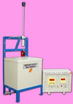
The apparatus consists of a small test sphere. This sphere is heated by a hot bath, till the steady state is reached and then it is coolled in air or water / oil. During both, heating and cooling of sphere, temperature of sphere is a function of time and hence, it is a unsteady state of heat transfer process. The temperature of sphere is measured by thermocouple. The hot bath is provided to heat sphere with temperature controller to facilitate to conduct experiment at different temperatures.
Specifications:
Test piece with thermocouples - 2 No.s of different materials.
Hot bath with heater and controller.
Cold bath.
Digital Temperature Indicator.
15 Amp., 230 V.A.C. power supply.
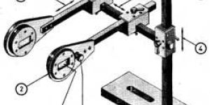
The unit is designed to study various governors, normally used to control the speed. The unit consists of a main spindle driven by a variable speed motor mounted on a base plate. The spindle is driven by belt & pully system. The optional governor out of four governor assemblies can be mounted on a spindle. The spindle speed can be controlled by speed control unit provided. A graduated scale is provided to measure the displacement of sleeve.
The centre sleeve of portal and proell governors incorporates a weight sleeve to which weights may be added. The Hartnell governor provides means of varying spring compression level. This unables the Hartnell Governor to be operated as a stable or unstable governor.
The governor speed is increased in steps to give suitable sleeve movements possible. The speeds and displacements are recorded. The results may be plotted as curves of speed against displacements. Further tests are carried out by changing variables.
Specifications
Drive Unit - D.C.Motor,1/4 HP, 1500RPM.
Speed Control Unit.
Belt and Pully system to give spindle speed 100 to 500 RPM.
Governor Mechanisms with springs and weights for following Governors -
Watt Governor.
Porter Governor.
Hartnell Governor.
Proell Governor.
Range of Experiment
Determination of characteristic curve of sleeve position against speed of spindle.
For Porter and Proell Governor Effect of varying mass of sleeve.
For Hartnell Governor Effect of varying spring compression.
Service Required
230V.A.C.Single phase stabilised supply.
Handheld Tachometer.
Rigid Floor Space - 1.5m X 1.5m.
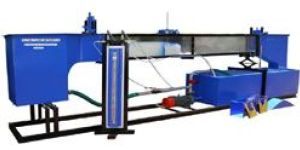
The tilting flume is designed to conduct various experiments at various bed slopes from 1 in 25 in upstream to 1 in 25 on down stream. The flume has a perspex window to visualize the flow over models fixed in flume. The flume is provided with gates on upstream & downstream side to control the flow. Students can thus conduct the experiments and also visualize the flow. Various experiments like open channel flow study, specific energy curve, hydraulic jump, calibration of weirs, notches and venturi flume can be conducted.
Specifications:
Flume - Cross section 200 wide x 300 mm. deep, length 4 meters, provided with sliding gates, one at upstream and one at downstream side & flow settling chamber at inlet. Screw jack at down stream side to change slope of bed from 1 in 25 in upstream to 1 in 25 in downstream and scale. Transparent window for visualization of flow.Overall length of flume is about 5.5 mtrs.
Notches -
Rectangular notch with flume fitting fixture. (G.M.)
600 V notch (brass) with flume fitting fixture.
Trapezoidal Notch.
Weirs -
Sharp crested weir - 1 no.
Broad crested weir - 1 no.
Ogee weir - 1 no.
Venturi flume.
Experiment on Hydraulic jump.
Trolley mounted point gauge for level measurement of water. Trolley can be traversed for whole length of flume.
Venturimeter & differential manometer for measurement of flow.
2 HP pump and sump tank for recirculating the water.
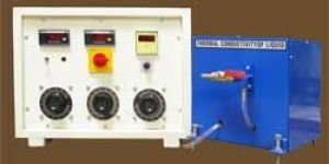
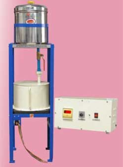
Thermal conductivity of solids, liquids and gases is one of the important property and its evaluation is of prime importance to engineers in different fields. The apparatus is designed according to Guarded Hot Plate method and useful to find out Thermal Conductivity of some commonly used liquids over a range from300C to 800 C. Guarded Hot Plate Assembly consists of a Hot Plate with electrical heater sandwiched between two aluminum plates. A Ring guard Heater and Top guard heater is used to prevent heat loss from hot plate. A cooling plate on opposite side of liquid removes heat from liquid. The whole assembly is placed in an enclosure to prevent heat losses. A control panel is provided to control and measure heat input and temperature.
Specifications:
Guarded Hot plate assembly comprising of Main heater, Ring Guard heater and Top Guard heater & cooling plates with valves.
Enclosure to house Guarded Hot Plate assbly.
Thermocouples.
Instrumentation & Controls :
Digital Voltmeter - 0 - 199.9 Volts.
Digital Ammeter - 0 - 1.999 Amp.
Multy channel Digital Temperature Indicator.
Dimmer stat - 0 - 2 Amp.- 3 No.
Service Required :
230 V.A.C. stabilized supply with earthing.
Floor space - 1.5m X 1m at working height.
Water supply at rate of 10 LPM at constant head.
The apparatus consists of a copper sphere in which a mica heater is fitted. This small sphere is surrounded by another copper sphere and the insulating powder to be tested is filled in between these two spheres. The heat produced by heater is radially flows outwards in all directions through insulating powder. A digital temperature indicator is used to measure temperatures of Inner & Outer sphere. An ammeter & voltmeter is provided to measure heater input. By knowing heat input and temperatures, thermal conductivity of powder can be calculated. The unit is provided with asbestos powder, however any other powder can be tested with this unit.
Specifications:
Inner sphere - copper - 100 mm. dia.
Outer sphere - copper - 200 mm dia.
Heater – Mica heater placed in inner sphere.
Thermocouples on outer surface of inner sphere and inner surface of outer sphere.
Instrumentation & Controls :
Digital Voltmeter - 0 - 199.9 Volts.
Digital Ammeter - 0 - 1.999 Amp.
Multy channel Digital Temperature Indicator.
Heater Control.
Service Required :
230 V.A.C. stabilised supply with earthing.
Floor space - 1.5m X 1.5 m at working height.
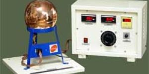
The apparatus is designed to determine the Stefan Boltzman constant. The apparatus consists of a hemisphere fixed on a backlite plate, the outer surface is surrounded by a hot water jacket. Hot water to heat the tank is obtained from a hot water tank with heater fixed above hemisphere. Hot water jacket heats the hemisphere and this heat is transferred to a small copper test disc by radiation. This small test disc can be introduced at the center of hemisphere. A thermocouple is provided at the canter of disc to measure the temperature of disc. With the help of Timer/Stop Clock change in temperature with respect to time can be recorded. The average temperature of hemisphere can be measured by four thermocouples placed on hemisphere.
Features: Easy understanding of phenomenon of heat transfer by radiation. Determination of Stefan Boltzman constant. Built in timer for temperature measurement at constant intervals.
Specifications:
Hemisphere made of copper, 200 mm dia, approx.
Hot water jacket.
Test Disc - 20 mm dia., 1.5 mm thick, copper
Hot water tank with heater.
Instrumentation & Controls :
Multy channel Digital Temperature Indicator.
Experimentation :
Determination of Stefan Boltzman Constant.
Study of effect of hemisphere temperature on the constant.
Service Required :
230 V.A.C. stabilized supply with earthing.
Floor space - 1.5 m X 1.5m at working height.
The test rig consists of suitable equipment for performing experiments to measure the steam turbine efficiency, steam quality, and flow rate and condenser effectiveness. The turbine is suited for operation with a 300kghour, 10bar saturated steam supply.
The test rig consists of suitable equipment for performing experiments to measure the steam turbine efficiency, steam quality, and flow rate and condenser effectiveness. The turbine is suited for operation with a 300kghour, 10bar saturated steam supply.
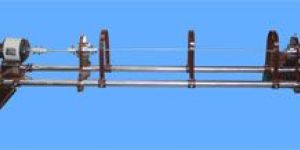
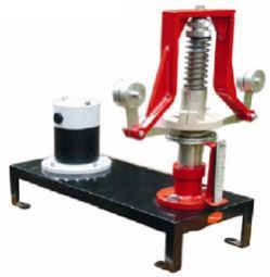
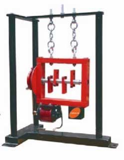
The apparatus enables the students to experimentally balance a rotating mass system and to verify the analytical relations. The apparatus consists of a steel shaft fixed in a rectangular frame.A set of four blocks with a clamping arrangement is provided. For Static balancing, each block is individually on shaft and relative weight is found out using cord and container system in terms of number of steel balls.
For dynamic balancing, a moment polygon is drawn using relative weights and angular and axial positions of blocks are determined. The blocks are clamped on shaft is rotated by a motor to check dynamic balance of the system.
The system is provided with angular and longitudinal scales and is suspended with chains for dynamic balancing.
Specifications
Drive Motor-FHP,Universal Motor.
Balancing Weights-4 No.s with different mass for varying unbalance.
Cord & Container with stell balls for relative weight measurement.
Range of Experiment
Static balancing of system using steel balls.
Dynamic balancing of a simple rotating mass system.
Observation of effect of unbalance in a rotating mass system.
Service Required
230Volts, AC Single Phase stabilised power supply.
Space- .75m X 1.5m area at working height.
An instruction Manual will be supplied along with unit.
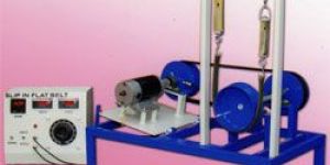
The apparatus consists of a variable speed D.C.Motor, Driving pulley and Driven pulley of equal diameter. The pullies are mounted on input shaft (Motor shaft) and output shaft. The driven pulley can slide on the base with bearing block to change initial tension in belt. Brake drum is mounted on output shaft helps to measure power output. The motor speed is varied by dimmerstat. A two channel RPM Indicator is provided to measure speeds of driven and driving pullies respectively.
Specifications:
D.C.Motor - 1 HP, 1500 RPM, variable speed.
Driving & Driven pullies of equal diameters.
Brake drum along with spring balance.
Flat Belt of fixed length of following materials -
Fabric Belt.
Canvas Belt.
Rubber Belt.
Belt tightening arrangement.
Speed Controller unit.
Two Channel digital RPM Indicator.
Experimentation :
To measure power transmitted with varied belt tensions and plotting graph of (T1 - T2) Vs. (T1+T2)/2 ie 'Tension Characteristics'.
To measure percentage slip at fixed belt tension by varying load on brake drum and plot graph of (T1-T2) Vs. percentage slip ie. 'Slip Characteristics'. Finding a creep zone from graph.
To measure belt slip speed and observe the limiting value of load at constant speed when the slip just starts.
Service Required :
230 V.A.C. stabilised power supply.
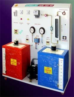
ESCRIPTION:
The REFRIGERATION test rig works on simple vapour compression refrigeration cycle and uses R134a as a refrigerant. It is environment friendly. The system is fabricated such that students can observe and study vapour compression cycle, its component principle & working. The arrangement of parts such that, all the parts are visible and working can be easily understood.
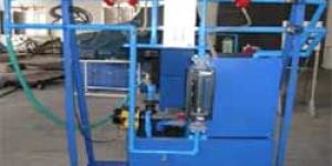
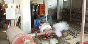
Test rig consists of a Pelton wheel water Turbine, designed for laboratory experimental purposes and to conduct test in metric units. The specifications of the turbine are as follows:- Design Speed - 1000 RPM. Output Power - 1.0 KW The turbine consists of a cast iron body with a large transparent acrylic window, a nozzle and spear arrangement, a rotor assembly of shaft, runner and a brake drum all mounted on a sturdy base frame. The pelton buckets and nozzle are made of gun metal and the spear made of brass for corrosion resistance. The input to the turbine is controlled by adjusting the spear position with a hand wheel. A rope brake arrangement with a spring balance is provided for loading the turbine. The transparent perspex sheet side casing is provided for visual observation of flow on the buckets. Water inlet pressure is measured by a pressure gauge.
Water to the turbine is provided by a centrifugal monoblock pump set of 5 HP capacity. The pump operates on 440Volts, 3 Phase, 50 Hz line.
Other standard accessories include a DOL starter, switch, flow control gate valve, suitable piping.
Flow measuring unit consists of a venturimeter with pressure taps connected to two pressure gauges mounted on a panel board.
The complete test rig is mounted on a storage tank of suitable capacity. The tank is provided with FRP lining for total rust protection
By photoelasticity principles, a diffused light or lens type polariscope, generates the data of principle stress difference at various points on the model. But when these values of shear stress are not sufficient for our purpose and when we desire to have separate values of principle stresses at a point, we adopt some more means of separating these stresses. Shear difference method, oblique incidence method, electric analogy method are various methods used for this purpose
Shear difference method is a theoretical mathematical method of separating the stresses. But this method is very tedious and time consuming and often needs a computer for analysis of complete model. Electric analogy method, which works on laplace equation, needs very costly equipment. Oblique Incidence method is a method of separating the principle stresses in which one more relation between two principle stresses is obtained by directing the light incident on model on oblique angle.
An Equipment – This is a simple device to be used as on accessory along with a polariscope. It consists of a pair of prisms fitted in two separately rotable prism holders. These prisms change the direction of light incident on it. A prism on light box side deflects the light in 450 A second prism makes this oblique ray of light, parallel to original ray of light. So the model kept between two prisms, receives a light ray at an angle, which is 450 in this case. A scale reads the angular position of these prisms. A linkage fabricated from square bars is provided to adjust the X , Y and Z co-ordinates of prism so as to reach at the point of interest.
Now a days gyroscope is a very important tool used for various controls in high technology vehicles. For minimising rolling, yawing and pitching of ship or air craft Gyroscope is used. Balloons use Gyroscope for controlling direction. Gyroscope has applications in space craft, space platforms. Thus study of Gyroscope is of high importance for any Engineering student.
Description
The Motorised Gyroscope consists of a disc rotor mounted on a horizontal shaft rotating in the ball bearings of one frame. The rotor shaft is coupled to a motor mounted on a trunion frame having bearings in a yoke frame which is free to rotate vertical axis. Thus the disc can be rotated about three perpendicular axis. Angular scale and pointer fitted to frame helps to measure precession rate.
Features
Demonstration of relationship between applied torque and precession rate alongwith direction of rotation.
Gyroscopeic couple easily varied by weights.
Precisely balanced rotor.
Useful to verify the relationship- T=lw.wp
Specifications
Disc Rotor- 30 Cm. dla., 10mm thick approx.
Drive - FHP, AC/DC Single Phase Motor.
Dimmerstat to vary speed of motor.
Weight Set.
Range of Experiment
Observation of Gyroscopic behavior( Two Laws of Stability )
Experimental justification of the equation T=lw.wp For calculating the Gyroscopic couple by observation and measurement of results for independent variations in applied couple T and precession wp.
Service Required
230Volts, A.C.stabilised supply.
Tachometer.
1m X 1m space at working height.
The unit is designed to provide visual demonstration and measurement of longitudinal and transverse pressure distribution over Michell Thrust Bearing. Students can vary speed, gap and viscosity of oil. It gives visual demonstration of cavitaion. The unit consists of a belt moving on two identical pulleys driven by variable speed d.c.motor. The belt passes through a oil tank and carries oil film along with. This oil passes through tilting pads and develops pressure, which is measured by manometer through pressure tapings on tilting pad. Different types of pads can be used.
Specifications:
Drive Motor - 0.5 HP, 1,500 RPM, variable speed D.C.Motor with speed controller.
Tilting Pad -
Convergent Type - Rectangle
Convergent Divergent Type - Rectangular.
Multitube Manometer.
Manometer for cavitation demonstration.
Oil Tank - 0.5 X 0.2 X 0.2 m approx.
Loading arrangement on pads.
Experimentation :
Determination of pressure development.
Plotting pressure Variation curve in longitudinal & Transverse direction of a pad for various speeds.
Demonstration of cavitation phenomenon.
Service Required :
230 V.,A.C. stabilised power supply.
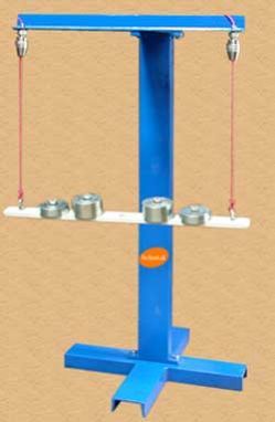
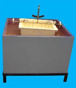
Specifications:
M. S. tank size 0.7 x 0.7 x 0.3m with a drain plug as a storage.
A hollow ship model with balancing weights.
Circular weights 4 in numbers to be used as cargo or warship loads.
Tilting weights 4 in number for balancing.
A pendulum & graduated are for measuring tilt angle.
Range Of Experiment:
Determination of metacentric height of warship.
Determination of metacentric height of cargo ship.
Service Required :
Suitable table to mount the equipment else it can also be kept at the ground level.
Test rig consists of a battery of 12.5mm pipes of stainless steel, aluminium and copper of length over 100 times the diameter with pressure tappings at either ends to measure the losses due to pipe friction - major losses. To measure the minor losses, a 15mm(1/2") GI pipe is fitted with a bend, an elbow, a sudden enlargement and a sudden contraction. Suitable flow control valves are provided in all the pipe lines.
Each test pipe and pipe fitting is provided with pressure tappings to measure the pressure loss. A differential manometer (without mercury) is provided to measure this pressure loss. The pressure tappings are connected separately to a manifold which in turn is connected to the manometer for easy change over. A strong iron stand is provided for supporting the pipe lines. A stop watch and an M.S. collecting tank of size 90 liters. with a gauge glass scale fitting, a drain valve and a bend are provided to measure the actual flow rate.
A 220 volt AC, 0.5 HP, single phase monoblock ISI pumpset with suitable pipe fittings, strainer foot valve, and switch is provided to supply water to the test rig.
A sump tank of size 200 liters with suitable drain is provided to store the water. A strong iron stand fitted with wheels supports the complete test rig. The unit is moveable. All tanks are provided with FRP lining for total rust protection
The apparatus consists of a plain shaft encased in a bearing and directly driven by a small motor. The bearing is freely supported on the shaft and sealed at motor end. The motor speed is precisely controlled by control unit. The bearing contains twelve equispaced pressure tappings around circumference and four along the axis. All tappings are connected by light flexible plastic tubes to the manometer so that the pressure head of all sixteen points can be observed at a time. The bearing can be loaded be attaching weights to the arm supported beneath it.
Experiments :
Observation of the pressure profile at various conditions of load and speed.
Plotting the cartesian and polor pressure curves.
Plotting the theoretical Sommerfield curves.
Service Required :
A.C,Single Phase .230 V. stabilized power supply.
Control Panel for speed control.
Manometer Board(Sixteen Tube)
Oil recommended - SAE 30/40.