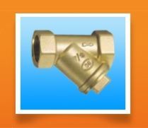
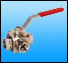
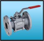
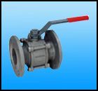
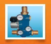
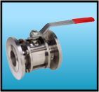
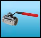
hydraulic features
filters used for heating, sanitary systems, compressed air, water distribution.
technical features
max inlet working pressure:
(mod.246) 10 bar
(mod.249) 25 bar
(mod.250) 25 bar
(mod.114.5) 25 bar
max temperature (water):
(mod.246) 80°c
(mod.249) 150°c
(mod.250) 150°c
(mod.114.5) 150°c
max inlet working pressure:
uni iso 228/1
construction
mod.250:
size ½" - 2" in brass en 1982 - cb753s
mod.246:
size ½" - 1" in brass en 12165 - cw617n
size 1"¼ - 2" in brass en 1982 - cb753s
mod.249 (114.5):
size ½" - ¾" in brass en 12165 cw617n
size 1"- 2" in brass en 1982 - cb753s
size 2"½ - 4" in bronze uni 7013-72
cartridge made of stainless steel washer plug na 1030.
HYDRAULIC FEATURES
The "HAMMER STOP" device has been designed in order to attenuate the "water hammer" phenomenon which is created in a closed conduct when there is a abrupt variation of the fluid speed. This phenomenon presents itself when there is quick sequence of pressure excesses and drops which creates instability and generates noise and which can provoke serious damages to the systems and the connected devices. The water hammer damper must be installed near to the devices which can trigger this event such as ball valves, solenoid valves, mixing valves and all hydraulic components capable of stopping the water flow in the pipelines in a sudden way. The norm UNI 9182 "Installations for the alimentation and distribution of cold and hot water. Criteria regarding design, tests and management" recommends the use of a water hammer damper.
TECHNICAL FEATURES
Pressures :
Static working pressure
3 bar
Maximum working pressure (PN)
10 bar
Maximum water hammer
50 bar
Temperature :
Maximum working temperature (TS)
90° C
Compatible fluids :
Water
Threading:
Pipeline connection
Threads according to ISO 228/1
Requirements and tests as per :
Shell tightness
Test P11 - EN 12266-1
Requirements and tests as per worksheet KIWA BRL K632/03
DESIGN
Body in brass EN 12165 - CW617N chrome plated with ELECTRODEPOSITED COATING EN 12540 (Cu/Ni5sCrr)Damper in brass EN12165-CW602N (DZR)SM GALVANIZED STEEL calibration spring - EN 10270-1MStatic and dynamic sealing gaskets in EPDM "perox"
PRODUCT CODE
0198.015 male ½"
0198 . ½"
WATER HAMMER DAMPER "HAMMER STOP"
CONNECTION: MALE
Features (external dimensions)
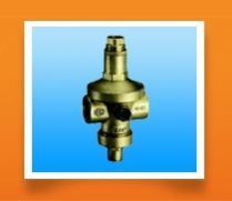
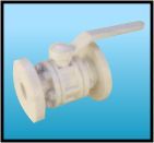
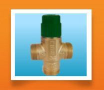
HYDRAULIC FEATURES
Models suitable to reduce pressure (max 16 bar).
TECHNICAL FEATURES
Max inlet working pressure: 16 bar Setting: min. 1, 5 max 7 bar Variation % of the setting changing the inlet pressure: ± 5% Max temperature (water): 80°CPre-setting: 3 barThreading for Waterworks: UNI ISO 228/1. Manometer joint: ISO 7/1
CONSTRUCTION
Sizes ⅜" - 1" in brass UNI EN 12165 - CW617N Sizes 1"¼ - 2" in brass UNI EN 1982 - CB753S NBR diaphragm with textile insertsSeat washers and washers in NBR rubberStainless steel seat AISI 303
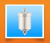
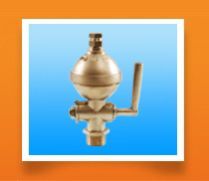
introduction
vacuum & safety valves is suitable for all kinds of water heaters and the container and steam system.
using method
vacuum & safety valves is suitable for all kinds of water heaters and the container and steam system. When water heater and steam system present the vacuum state, can open the system that originally closed automatically, make it dispel the vacuum state that may appear while entering air. Prevent from because siphon water in being function systematic take out and cause container collapse or water heater wait for device to be braised to burn.
technical parametervacuum:
UV-B lamps emit ultraviolet rays between 280nm and 360nm (at peak 306nm). The spectral energy distribution suits to test the ultraviolet resistance of paints, plastics and rubbers. They are also used for the special light sources for inspection and analysis.
UV-B lamps emit ultraviolet rays between 280nm and 360nm (at peak 306nm). The spectral energy distribution suits to test the ultraviolet resistance of paints, plastics and rubbers. They are also used for the special light sources for inspection and analysis.
the shape, structural, electrical characteristics are the same as those of general fluorescent lamps used for illumination* 1 after 100 hours lighting.* 2 when the ultraviolet ray output becomes 60% of the initial output (after 100 hours lighting).
warning
the radiation of those lamps is harmful to eyes and skin.protect your eyes and your skin against the ultraviolet rays.
uv-b lamps emit ultraviolet rays between 280nm and 360nm (at peak 306nm). The spectral energy distribution suits to test the ultraviolet resistance of paints, plastics and rubbers. They are also used for the special light sources for inspection and analysis.
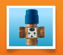
MAIN CHARACTERISTICS AND USES
The RA thermostatic mixings valves are used in hot water systems for sanitary use. They keep the temperature of mixed water supplied to the user constant even when the condition listed below vary:
Temperature
Supply pressure
Incoming hot and cold water flow
The RA thermostatic mixing valves have a temperature range that is ideal for heating a centralized water system with heater . They also have an internal anti-limestone lining.OPERATION : The valves were designed to supply domestics hot water at an adjustable and constant temperature where no other regulating system is present. The very sensitive thermostatic elements is positioned centrally inside the out going stream union and its guides a regulating shutter which adjusted the ingoing cold water flow to the hot water flow according to the required water temperature . The knob can be used to regulate the temperature of the outgoing water. MATERIALS :
Shutter - Brass
Body - Brass
Tap - Brass
Spring - Stainless steel
Knob - PA6
OPERATION INSTRUCTIONS
Using Method: Temperature & Pressure relief valves is suitable for bearing the pressing type solar water heater, gas heater, electrical heater, water heater of fuel, water heater of heat pump, sensitive function heater, etc. Various kinds of heaters (such as the boilers) and hot water containers, can lower the temperature and reduce pressure automatically, have temperature and pressure double safe protection function.
TECHNICAL PARAMETER
Standard Setting: 75, 87,100, 125,150psi (0.517, 0.6, 0.69, 0.86, 1.034MPa)
Temperature Relief: 210°F (99°C)
Dimensions / Weight
Can also confirm that exactly makes the pressure & exactly make temperature according to the needs of user's contract for future delivery.
INSTALLATIONTemperature and Pressure Relief Valves should be installed on the water heater top or side. The temperature sensing element must be immersed in the water within the top 6" of the tank. The eliminating pipeline should be installed under the relief valve. Its terminal station distance in floor drain should be greater than 6" to make it easily remove & observe water.
SAFEGUARD & MAINTENANCE
After installing, water heater users must lift the relief valve handle once at least every year, so as to ensure that unblocked things in the waterway of the relief valve. Before operating handles, please check the elimination pipeline which joining the relief valve guaranteed that the hot water from relief valve discharge the proper place, otherwise it may cause the bodily injure. If the handle is lifted, without water flowing out, it proves that the relief valve is invalid. Then it should turn off the water heater and ask pipeline personnel check and repair
HYDRAULIC FEATURES
This automatic air vent valve is a single float valve designed for solar thermal energy plants, and carries out two main functions: the evacuation of a consistent air flow through the system (e.g. during loading/pressurization of the plant), and degassing which discharges air trapped in the pipeline, while functioning, in particular in the solar collectors. This valve has a paramount importance in solar thermal energy plants, evacuating and discharging trapped air in the pipelines and in the solar collectors. As a matter of fact, the presence of oxygen in the system can provoke numerous negative phenomena such as anodic corrosion, localized noise, air pockets, obstructions, etc., which may significantly compromise the performance and integrity of the systems. These valves are usually installed at the summit of the primary circuit in a solar thermal energy plant, and are resistant to the high temperatures that the heat-transfer fluids can reach, even in stagnation phases. Their suitability for application in solar thermal energy plants conforms to EN 12976 and EN 12977.
TECHNICAL FEATURES
Pressure :
Maximum allowable pressure (PN)
10 bar
Minimum sealing pressure
0.2 bar (Grade A according to EN 12266-1)
Range of operation air evacuation
from 0.5 bar to 5 bar (tolerance ± 10% max. detected)
Temperature :
Maximum allowable working temperature (TS)
180° C (200° C in brief periods)
Compatible fluids :
Glycolate solutions (glycol)
water and fluids Group 2
Heat transfer fluids in compliance with Italian national standards (UNI 8065 § 6)
Generic Fluids
50%
Threading:
Pipeline connection
Threads according to ISO 228/1
Requirements and tests as per :
EN 1074-4
DESIGN
Body and Plug in brass
EN 12165 - CW617N
Seat and internal mechanisms
Brass - EN 12164 - CW614N
Gaskets and o-ring
FLUORINATED RUBBER (VITON - FPM)
Spring and counterweight
STAINLESS STEEL EN 10088-14310 (AISI 302)
Nickel plating ELECTRODEPOSITED COATING EN 12540 (Cu/Ni5s)
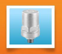
The "ROMA" model automatic air vent is an automatic valve with single float, used for the evacuation and discharge of large volumes of air from water supply pipes. The integrated tap device is equipped with a dual position 90° male seal. Position "A" communicates the system with the upper air discharge recess while position "B" bypasses the system discharge recess and permits its draining through the front slot. This renders it particularly ideal for installation in zones outside buildings where there is a high risk of freezing. The "ROMA" air vent valve may only be installed vertically. In order to maximize the efficiency of the discharge, it should be installed at the highest points in the system or, if this is not possible, a TEE fitting should be installed at the input, as in figure "C". When installing it at the top of an ascension pipe, a conveyable discharge hose can be installed (option available only on request). The particular spherical profile of the internal floater-obturator in special thermoplastic rubber forestalls water spatter during the sealing phase, in closure. The absence of sliding guides, hence drag, allows the spherical floater an elevated velocity and precision in closing besides avoiding dangerous incrustations. At the discharge outlet there is a protective catch for dust and lint, which, over time, could deposit upon the opening of the cap, obstructing it; moreover, being perforated, anti-tampering seals may be used in compliance with legislation currently in force.The lower anti-spray guard allows the hydraulic thrust to be distributed evenly across the entire surface of the sphere, limiting the turbulence to a minimum and guaranteeing a highly precise closure. The "ROMA" model air vent is used in conditioning plants, sanitary installations for water distribution destined for human consumption outside buildings under EN 805, and irrigation plants. Maintenance of the "ROMA" model air vent consists in the periodic verification of the closure of the integrated stop device. The male obturator can be checked by tightening the front hexagonal nut while moving the lever from position "A" to position "B" and vice versa. The lever should only be actioned manually and not with the help of any tools. In the event of water outflow from the upper seat of the air vent, substitute the internal sphere-obturator, which is easily accessible by dismounting the body cap. In case of prolonged inactivity, the device should be disinfected according to EN 805 §12. This product adheres to the standards set forth by the international health authorities for the transport of alimentary fluids and potable water.
The "ROMA" model automatic air vent is an automatic valve with single float, used for the evacuation and discharge of large volumes of air from water supply pipes. The integrated tap device is equipped with a dual position 90° male seal. Position "A" communicates the system with the upper air discharge recess while position "B" bypasses the system discharge recess and permits its draining through the front slot. This renders it particularly ideal for installation in zones outside buildings where there is a high risk of freezing. The "ROMA" air vent valve may only be installed vertically. In order to maximize the efficiency of the discharge, it should be installed at the highest points in the system or, if this is not possible, a TEE fitting should be installed at the input, as in figure "C". When installing it at the top of an ascension pipe, a conveyable discharge hose can be installed (option available only on request). The particular spherical profile of the internal floater-obturator in special thermoplastic rubber forestalls water spatter during the sealing phase, in closure. The absence of sliding guides, hence drag, allows the spherical floater an elevated velocity and precision in closing besides avoiding dangerous incrustations. At the discharge outlet there is a protective catch for dust and lint, which, over time, could deposit upon the opening of the cap, obstructing it; moreover, being perforated, anti-tampering seals may be used in compliance with legislation currently in force.The lower anti-spray guard allows the hydraulic thrust to be distributed evenly across the entire surface of the sphere, limiting the turbulence to a minimum and guaranteeing a highly precise closure. The "ROMA" model air vent is used in conditioning plants, sanitary installations for water distribution destined for human consumption outside buildings under EN 805, and irrigation plants. Maintenance of the "ROMA" model air vent consists in the periodic verification of the closure of the integrated stop device. The male obturator can be checked by tightening the front hexagonal nut while moving the lever from position "A" to position "B" and vice versa. The lever should only be actioned manually and not with the help of any tools. In the event of water outflow from the upper seat of the air vent, substitute the internal sphere-obturator, which is easily accessible by dismounting the body cap. In case of prolonged inactivity, the device should be disinfected according to EN 805 §12. This product adheres to the standards set forth by the international health authorities for the transport of alimentary fluids and potable water.
AUTOMATIC AIR VENT / AIR RELEASE VALVE
Automatic air vent valve prupose of installation in hot & cold water system to eliminate entrapped air in water lines. Prevent air locking due to filling of system or while priming of pump systems to increase thermal efficiency. To increase thermal efficiency fitted with check valve to prevent air being drawn back into system or water escaping from port event.
INSTALLATION: VERTICALLY
Valve body nickle plated in forged brass
Working temperatures 90°C
Working pressure range 6 bar - test pressure 16 bar
EPDM valve head
Float: plastic float (PP resin)
Lever: ASTM C36600
Spring: AISI 302
PRODUCT SIZE
12 - M - 3/8"
15 - M - 1/2"
20 - M - 3/4"
25 - M - 1"
RAW SERICE TERMOSTATIC MIXING VALVES
MAIN CHARACTERISTICS AND USES : The RAW thermostatic mixing valves are used in hot water systems for sanitary use. They keep the temperature of the mixed water supplied to the user constant even when the condition listed below it
Temperature
Supply pressure
Incoming hot and clod water flow
The RAW thermostatic valves have a temperature range that is ideal for heating a centralized water system with heater.
OPERATION : The valves were designed to supply domestic hot water at an adjustable and constant temperature where no other regulating system is present. The very sensitive thermostatic element is positioned centrally inside the outgoing stream union and it guides a regulating shutter which adjusts the incoming cold water flow (C fig.2) to the hot water flow (H fig.2) according to the mixed water temperature (MIX fig.2) . The knob can be used to regulate the temperature of the outgoing water. There Is also a hot water locking system in case the supply of cold water is stopped (anti- scald system)
MATERIALS
Shutter - Brass
Body - Brass
Tab - Brass
Spring - Stainless steel
Knob - PA6
FUNCTIONAL CHARACTERISTICS :
Nominal pressure : PN 10
Regulation field : 30° 60°C
Max. Working pressure (static): 14bar
Max. Working pressure (dynamic):5 bar
Max. ingoing temperature:85° C
Max. ratio between the input pressures (H/C or C/H):2:1
Threads : internal and External ISO228/1
quartz sleeves are of tremendous benefit in that they provide protection for lamps without sacrificing efficiency. Sleeves protect against such common problems as breakage, leakage, temperature fluctuations, and environmental hazards. They are an investment worth making.
our quartz sleeves provide the following benefits:
useful for applications in small spaces
innovative two-tube linear technology
top quality materials and engineering
customized, proprietary design options
The ozone lamp(a short-wave germicidal lamp) made of quartz glass transmits UV rays at 185nm wave length that generates ozone, as well as germicidal UV rays at 253.7nm. The ozone lamp is best used for photomask and display cleaning, surface treating, air-disinfecting and deodorizing purposes.
The ozone lamp(a short-wave germicidal lamp) made of quartz glass transmits UV rays at 185nm wave length that generates ozone, as well as germicidal UV rays at 253.7nm. The ozone lamp is best used for photomask and display cleaning, surface treating, air-disinfecting and deodorizing purposes.
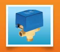
MOTORIZED 3-WAY ZONE VALVES WITH RETURN SPRING FOR HYDRAULIC CIRCUITS SERIES SF
MAIN CHARACTERISTICS : These are powered by an electric motor and can assume two operating positions depending on whether the motor is activated or not. One or two auxiliary switches can be installed on request. These are activated when the valve switches. The Valves are equipped with an external lever for manually positioning the shut-off ball in its central positing.
FUNCTION: Without electric power supply, the valve is positioned as shown in flig.1: Port A closed Port B open. The ball valve closes port a thanks to the elastic force exercised by the return springs. When it is powered, the servomotor overcomes the spring force and moves the ball form port A to B in about 20 Seconds and keeps it in that position until the electric power supply is shut off. When the electric power supply is shut off the return spring brings the shut-off ball back to port A.
USING THE MANUAL LEVER: A lever is located on the side of the motor. This is used to position the shut-off ball in an intermediate positing (fig. 3). This is helpful when filling or emptying the heating system. The lever reset, form manual to automatic, takes- place automatically whenever the valve is electrically by activated.
FUNCTIONAL CHARACTERISTICS :
Rated supply voltage 230 Vac. (Available: 24, 110 Vac.; 50HZ)
Absorbed power 5/6 W
Degree of protection IP22 IES 529 Standards. European Standards Ref. CEI EN 60529
Aux. contact capacity 3 a, 250 Vac.
Maximum differential pressure: See Refer to Tab. Of Hydraulic Characteristics
Rated pressure PN 10 Kg /Cm (2)
Flow temperature limits +5 / 110 Degree C
Maximum room Temperature 60°C
Nominal opening time 20 sec.
Nominal closing time 6 Sec.
Standard Cable Length 1000mm.
AUXILIARY SWITCHES: A single pole micro switches (version M1), a two-pole micro switch (M1S version ) or two micro switches (M2 or M2 S version ) can be mounted on all versions.There is a special kit for mounting the single-pole auxiliary micro switch even in versions that do not carry it as an original part (M1 Kit.) .Kits M1S, M2 S cannot be installed in versions which do not mount them originally.
MATERIALS :
Valve body: Brass
Valve cover: Brass
Ball - bearing pin Brass
Return Springs Stainless steel
Motor cover Self - extinguishing ABS
APPLICATION EXAMPLES 1 AS three -WAY ZONE VALVE The zone room thermostat controls opening and closure of the respective SF valves. When there is no demand it shut off power to the valve, which closes the zone and recalculates water back to the boiler return? Installing a meter as shown in the diagram permits efficient sub-division of operating costs. The load loss of the recirculation pipeline should be balanced to avoid excess flow rate variation in other circuit during valve operation.Note: Do not install the valve upside down, with the valve cover below the valve body, as it is a potential container for eventual leaks or water condensation.
APPLICATION EXAMPLE GIVING PRIORITY TO THE HOT WATER HEATER We use this installation system mainly on combined boilers to permit the temperature of domestic hot water to be adjusted at the desired valve. The valve is used for priority over the heating system.
Secondary Business TypeManufacturer / Exporters / Wholesale Suppliers
Year of Establishment1994
No. of Employees6 - 20
Annual TurnoverRs. 0.5 to 2.5 Crore Approx.
Opening Hours
SUN : Closed
MON : 9:30 AM - 6:30 PM
TUE : 9:30 AM - 6:30 PM
WED : 9:30 AM - 6:30 PM
THU : 9:30 AM - 6:30 PM
FRI : 9:30 AM - 6:30 PM
SAT : 9:30 AM - 6:30 PM
Established in year 1994, Chintan Enterprise is Retailer of mixing valve, Mini Ball Valve, magnesium anode, Solar Air Vent, Diaphragm Pressure Reducing Valves, Valves With Stainless Steel Seat, Y Strainer Valve, TEMPERATURE, vacuum valves, thermostatic mixing valves from Mumbai, Maharashtra.