pressure loss bends fittings apparatus
65,000 / Piece
1 Piece (MOQ)
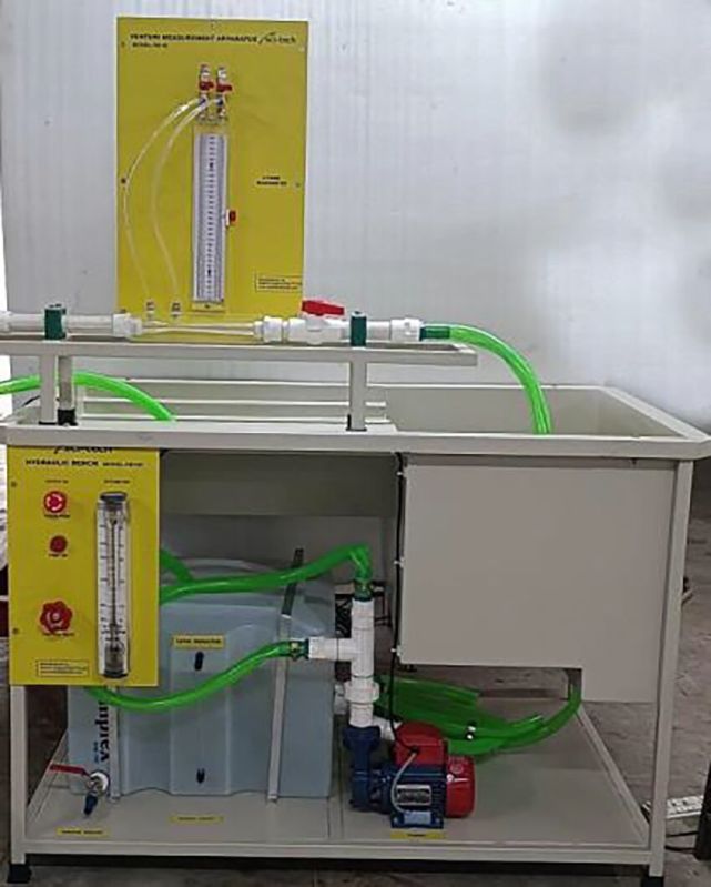
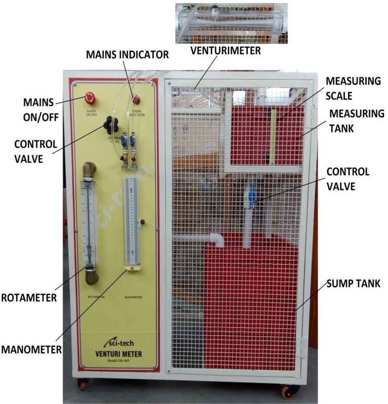
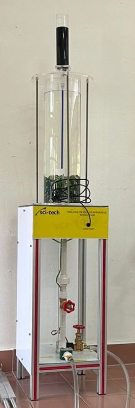
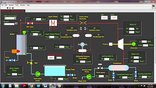
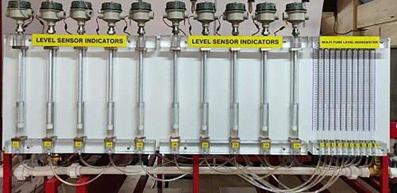
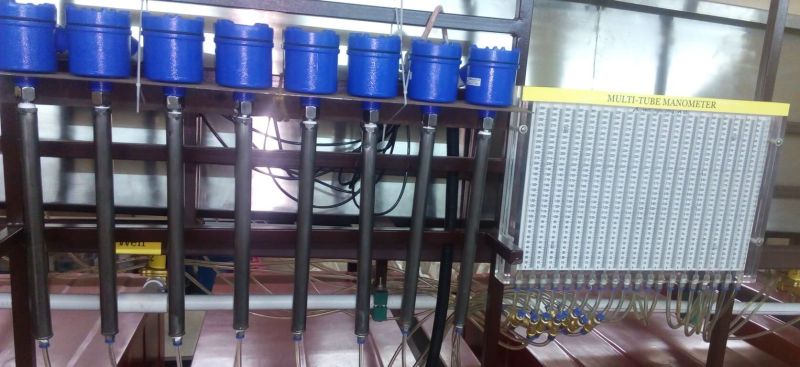
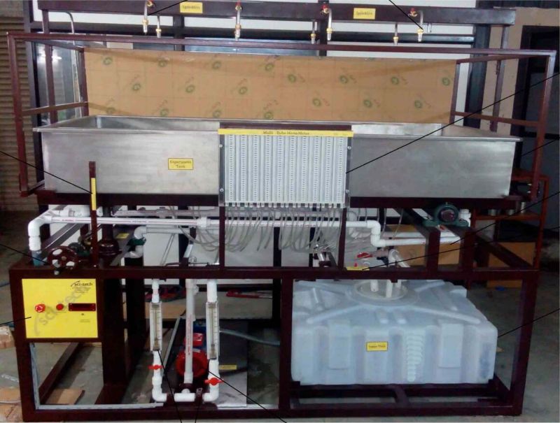
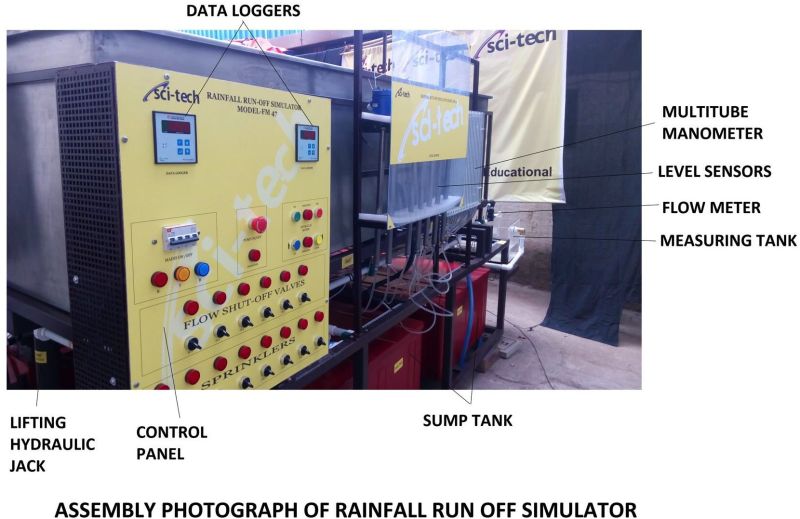
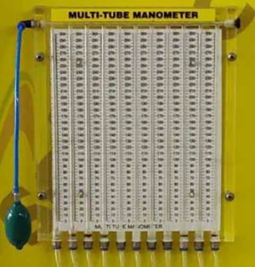
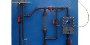
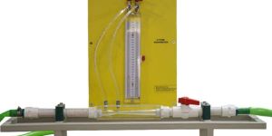
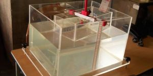
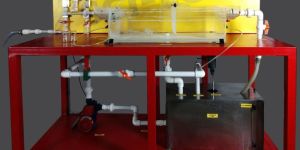
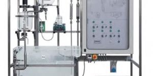
Study of pressure losses in bends and fittings in any pipe system is useful in view of the loss of head and consequent pumping power requirements. Sci-tech Pressure Loss in Bends and Fittings Apparatus Model FM05 is important equipment for any Fluid Mechanics and Hydraulics Engineering Laboratory of an educational institution. The Pressure Loss in Bends and Fittings apparatus has been designed to enable students to measure pressure losses across various types of bends and fittings in a typical pipe system. The apparatus, including the instrumentation for pressure measurements, is mounted in a robust vertical frame work mounted on wheels. The study devices include bends of small and large radius,450 mitre bend, 900 elbow, sudden enlargement and contraction and a gate valve. All these devices are equipped with pressure tapings both in the upstream and the downstream to measure the pressure drop. Pressure tapings across bends and fittings are connected to a multi-tube water manometer mounted on the frame work. A hand pump with a non-return valve is used to pressurize manometers. Pressure tapings across the gate valve is connected to the Bourdon tube pressure gauge. Another gate valve is provided at the downstream of the apparatus to vary the water flow rate through the devices. The FM 100 Hydraulic Bench or any other standard hydraulic bench models can be used to supply water. OPTION: Computer Based Learning Software is included to enable students understand and conduct experiments, tabulate results and plot graphs. The Pressure Losses in Bends & Fittings, is an important experimental set-up for any Fluid Mechanics and Hydraulics Laboratory of an educational institution. List of experiments: 1. Measurement of pressure losses across different kinds of bends, fittings and gate valve at various water flow rates. 2. Calculation of pressure loss co-efficient at various flow rates and comparison with the data available in the literature. 3. Comparison of pressure loss co-efficient for different bends. 4. Determination of pressure drop Vs flow characteristic curve for different openings of the gate valve. Important Features and Specifications: 1. Nominal pipe diameter: 25mm. 2. Pipe, bends and fittings made of Plastic. 3. Manometer, Range: 0-500mm WC, No. of tubes: 14, differential manometers: 7. 4. Enlargement diameter: 24mm. 5. Contraction diameter: 13.5mm. 6. Study devices : Short bend, large bend, 450 mitre bend, 900 elbow, enlargement, contraction, gate valve. Options: 1. A self contained unit of Pressure Loss in Bends and Fittings apparatus mounted on a mobile platform and with a flow controlled closed circuit water circulation unit consisting of centrifugal pump, flow meter, corrosion resistant sheet metal measuring tank and a sump tank will be supplied on request. 2. Other types of bends, fittings and valves for studies can be incorporated on request.
Country of Origin : India
Total Carbohydrate : 3yrs
Number Of Flower : Fluid Mechanics Lab Equipments
Condition : New
Brand Name : Sci-tech
 +4
+4
 +2
+2

 +1
+1

 +3
+3
 +1
+1

 +1
+1
 +4
+4
 +5
+5
 +2
+2
 +4
+4
 +3
+3
 +5
+5
 +5
+5
 +5
+5